


News & Exhibitions
Latest Factory Updates, Industry Trends & Global Exhibition Information
Wood Veneer Edge Banding Machines: Process Settings for Tear-Free, Clean Edges
A clean veneer edge is usually lost in the last few seconds of the edging cycle: the strip enters slightly misaligned, the pressure rollers crush a fragile grain line, the glue is too cool to wet the veneer properly, or a dull cutter pulls fibers instead of shearing them. The result may be small chips at the leading corner, a fuzzy trimmed edge, hairline cracks across the veneer face, or an edge that looks acceptable before sanding but breaks out during handling.
For a wood veneer edge banding machine, tear-free results come from matching five settings to the material condition: feed speed, adhesive temperature and spread, pressure-roller force, trimming geometry, and cutter sharpness. Do not treat these adjustments as independent controls. A higher feed speed, for example, may require more stable glue temperature and a sharper trimming unit; reducing roller pressure may prevent cracking but can reveal poor panel preparation or insufficient adhesive wetting.
Start by identifying where the damage begins
Before changing settings, inspect several rejected panels in sequence. The location and appearance of the defect usually point to the station that needs attention. A chipped edge after rough trimming is different from a crack that appears immediately after the pressure rollers. Operators can save time by separating bonding defects from cutting defects instead of increasing pressure, heat, and trimming depth all at once.
Look at both the face veneer and the trimmed edge under angled light. A white line or crushed area close to the edge often indicates compression before trimming. A rough, torn appearance confined to the cut line is more likely a tool or feed issue. When the defect follows the grain only in certain areas, veneer quality and grain orientation deserve as much attention as machine settings.
Prepare the panel edge and veneer strip before adjusting the machine
Edge banding cannot fully correct an inconsistent substrate. The panel edge should be square, clean, and free from saw marks, loose fibers, dust, release agents, or previous glue residue. Deep saw scoring can create gaps that require excess adhesive; the additional glue may then be forced toward the veneer face by the pressure rollers. That squeeze-out can contaminate the surface and make subsequent trimming less stable.
Check whether the panel edge is truly perpendicular to the face. A slightly beveled edge changes where the roller load is applied and can leave one side of a thin veneer under-supported. On lightweight board, damaged chipboard edges or open pores may absorb adhesive unevenly. A light pre-milling pass is often more useful than increasing glue output, because it creates a consistent bonding surface and removes material weakened by previous cutting.
Veneer strips need similar attention. Thin natural veneer reacts strongly to changes in moisture, temperature, and grain structure. Material stored in a very dry area can become brittle; material that has not stabilized after moving from a different environment may curl or fluctuate in width. Let strips rest under conditions reasonably close to the production area when possible. Do not assume that every roll or bundle will behave identically simply because it has the same nominal thickness.
Grain direction matters most at corners and on short panels. A cutter that performs cleanly when cutting with the grain can pull loose fibers where it meets a cross-grain section, cathedral figure, knot area, or repaired veneer. Marking the veneer feed direction during setup helps the operator recognize whether damage follows a material pattern or a machine pattern.
Set adhesive heat and feed speed as a pair
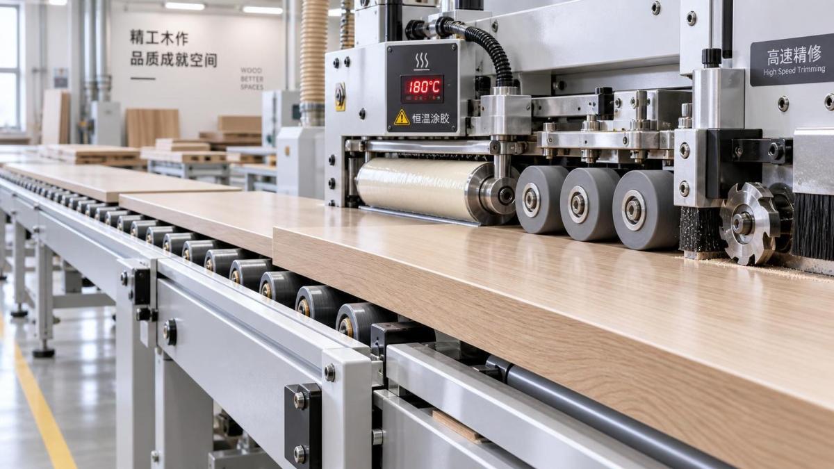
Adhesive must be fluid enough to spread uniformly and wet both surfaces, but it must not remain overheated long enough to degrade or create excessive penetration. Follow the adhesive supplier’s recommended operating range, then confirm the actual temperature at the glue pot rather than relying only on the displayed value. A sensor, heater, or control setting can drift, and a cold adhesive zone near the application roller may not behave like the bulk material in the pot.
When feed speed rises, the machine has less time to transfer adhesive, position the strip, and develop initial contact under the pressure rollers. A stable high-speed setup therefore depends on consistent glue viscosity, correctly set application rollers, and reliable pressure timing. If the line is slowed significantly, do not leave every other setting unchanged. Slower movement can increase heat exposure and alter adhesive behavior, especially during repeated stop-and-start operation.
Use the finished bond line as the practical indicator. After a controlled test piece has cooled sufficiently, inspect the edge for dry sections, starved areas, and excessive squeeze-out. A continuous but restrained glue line is preferable to a heavy bead forced onto the veneer face. If the bond is weak, first verify that both surfaces are clean and that the glue is reaching the panel edge evenly. Raising temperature without checking coverage can make the process less predictable rather than stronger.
Production interruptions require attention. Adhesive left at operating temperature while panels are not moving can change character, depending on the glue type and handling instructions. Restarting at full speed without a short trial piece may put a poor bond or overheated adhesive onto the next finished panel. Purge or stabilize the application system according to the adhesive and machine procedure before resuming critical work.
Pressure rollers should seat the veneer, not crush it
Pressure rollers have two jobs: bring the veneer into full contact with the adhesive and hold it in position while the adhesive begins to set. More pressure is not automatically better. With thin veneer, too much force can telegraph substrate irregularities through the face, create stress along the edge, and initiate cracks that only become obvious after trimming.
Begin with enough force to eliminate visible gaps along a straight test panel. Then inspect the veneer face beside the bond line. If there are compression marks, excessive glue squeeze-out, or repeated cracking at the same roller position, reduce force in small increments and retest. Roller alignment is equally important. A roller that contacts the upper or lower portion of the strip before the rest of the veneer may concentrate load on a narrow line.
The first roller normally establishes contact, while later rollers maintain it. Their settings should support a smooth progression rather than create abrupt changes in load. Confirm that rollers turn freely and that their surfaces are clean. Hardened glue on a roller can press a local ridge into the veneer, and a roller that does not rotate smoothly can drag the strip rather than compress it.
Watch the relationship between strip overhang and roller position
A small, controlled veneer overhang gives trimming tools enough material to create a clean finished edge. Excessive overhang, however, leaves a wider unsupported section that can vibrate or flex when it reaches the trimming station. Very little overhang may force the cutter to contact the finished edge too aggressively. Set the guides so the strip is centered consistently, then verify both top and bottom overhang on a test panel rather than judging only by the entry side.
Make the trimming cut small, sharp, and well supported
Most tear-out problems blamed on veneer quality are created or amplified by the trimming unit. The cutter must shear the material cleanly while the panel is supported against the guides. A worn insert, chipped knife, contaminated cutter, or loose spindle can leave an edge that looks torn even when the bond is sound.
Inspect cutter condition before changing feed speed. A sharp tool produces a clean cut with predictable resistance. A dull tool generates heat and pulling force, making delicate veneer more likely to fracture along the grain. Replace or rotate disposable inserts according to their actual edge condition, not only a fixed production interval. Abrasive veneer finishes, mineral contamination, and panel material all affect tool life.
Trimming depth should remove the intended overhang with the smallest practical amount of material removal. A deep cut asks the tool to remove more material, raises cutting force, and increases the chance of pulling fibers from a cross-grain section. Set the rough trim so it leaves a modest allowance for the finish trim where the machine design uses separate stages. The finish cutter should remove only what is needed to produce a flush edge.
Check cutter rotation direction and tool geometry against the machine configuration. Climb cutting and conventional cutting can produce different results depending on support, grain direction, and material thickness. There is no universal setting that suits every veneer, but the correct setup should keep the cutting force directed into a stable support condition rather than lifting the veneer away from the panel.
Vibration deserves a direct check. Listen for changes in spindle sound, inspect bearings and tool holders, and make sure pressure devices, guides, and conveyor components are holding the panel firmly. A panel that shifts slightly at the cutter can show intermittent chips that resemble a dull-tool problem. Test pieces should be long enough to reveal whether damage occurs only at entry, only at exit, or randomly through the cut.
Use corner and end-trimming settings to protect fragile grain
Leading and trailing corners are especially vulnerable because the veneer is not fully supported at the instant the tool enters or exits. If chipping is limited to corners, changing glue temperature is unlikely to solve it. Focus on panel guidance, end-trim synchronization, cutter sharpness, and the amount of material removed at the corner.
Confirm that the panel is detected consistently and that end-trim timing matches the actual panel length and feed movement. Mis-timed trimming can strike too early, leave an unsupported tail, or remove a larger section than intended. On short parts, frequent starts and stops can also affect conveyor stability. Run several pieces, not just one, before deciding that a timing change is correct.
For highly figured or brittle veneer, use a conservative finishing approach. Reduce the trimming load where possible, keep support close to the workpiece, and avoid forcing a high output rate that the material cannot tolerate. A production speed that is suitable for uniform melamine edging may be unsuitable for delicate natural veneer.
Do not use sanding to hide a bad trim
Scraping and sanding stations should refine a nearly clean edge, not rescue severe tear-out. Aggressive sanding can thin the veneer at the edge, round a profile that should remain crisp, or expose a lighter substrate line. It may also conceal the real source of the defect until panels reach assembly or finishing.
Set the scraper and sanding pressure lightly enough to remove minor cutter marks without digging into the veneer face. Check abrasive condition and keep dust extraction effective; loaded abrasives can heat the surface and leave burnishing or irregular marks. Inspect the edge after each downstream station. If the defect worsens after scraping, the scraper may be set too deep or its edge may be damaged.
When veneer is prepared in-house, control the upstream bond too
Some edge-quality problems begin before edge banding, particularly when face veneer or veneer-backed panels have been pressed with uneven temperature or pressure. A weakly bonded face veneer can lift at the panel edge during milling, gluing, or trimming. When this is suspected, inspect the panel before it enters the edge bander: lightly probe the face near the perimeter and look for loose areas, bubbles, or inconsistent adhesion.
For veneer and panel processing that requires controlled pressing, equipment such as a 200 Ton Hydraulic Hot Press Machine can support uniform clamping across large panel surfaces. Its 200-ton nominal pressure, three working layers, electric heating with heat-transfer oil, and maximum temperature of 150°C are relevant where press consistency is part of the panel preparation process. Press parameters still need to match the veneer, substrate, adhesive, and layup; stronger clamping alone does not correct unsuitable temperature or curing conditions.
A practical adjustment order for repeatable results
When defects appear, change one variable group at a time. Start with material and panel-edge condition, because no downstream station can reliably compensate for loose veneer, contaminated edges, or severe saw marks. Next verify glue temperature, spread, and roller cleanliness. Then set pressure rollers, followed by trimming tools, trimming allowance, and feed speed. This order prevents an operator from masking a dull cutter with slower production or hiding poor adhesive transfer with excessive roller force.
- Prepare several representative test panels, including the veneer grain and panel type causing the problem.
- Check edge squareness, veneer condition, glue cleanliness, guide alignment, and cutter sharpness before adjusting controls.
- Run a test at a moderate, stable feed rate and inspect the panel after bonding, trimming, and final finishing.
- Adjust one setting in a measured increment, then run enough pieces to confirm the result is repeatable.
- Record the proven combination of feed rate, glue setting, roller position, trimming allowance, and tool condition for that material.
A recorded setup is particularly useful when changing between veneer species, thicknesses, or panel substrates. It does not eliminate trial pieces, but it gives the next operator a reliable starting point. Clean veneer edges are rarely produced by a single “correct” setting; they come from a controlled sequence in which the panel is prepared well, the veneer is supported, the adhesive is stable, and the cutter removes only what it needs to remove.
Send Your Inquiry
We welcome your cooperation and we will develop with you.