


Too much pressure can crush a blockboard core; too little can leave weak glue bonds. The right setting must achieve bonding while limiting permanent compression.
For operators using a hot wood press for blockboard, that setting depends on core density, strip consistency, adhesive requirements, and the panel area under load.
Start with an approved adhesive and panel specification, calculate actual panel pressure, then validate trial panels after cooling. A hydraulic gauge reading alone is insufficient.
This guide explains how to translate press force into panel pressure, check compression, and adjust temperature and pressing time to reduce rejects and protect quality.
What Pressure Will Bond the Panel Without Crushing Its Core?
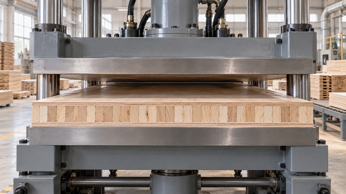
There is no universal pressure setting for every blockboard construction. A successful setting for dense, uniform strips may permanently compress a softer or uneven core.
Your working window lies between two limits: enough pressure to establish adhesive contact, and low enough pressure to preserve the required core structure and thickness.
Begin with the adhesive supplier’s recommended specific pressure, temperature, and pressing time for the application. Confirm that these recommendations cover your materials and panel construction.
Next, check the panel specification for finished thickness, allowable compression, and bond performance. Those acceptance criteria determine whether a trial setting is actually suitable.
If adequate bonding requires pressure that damages the core, investigate material preparation, adhesive application, and assembly conditions. Further pressure increases cannot resolve every bonding problem.
Evaluate the entire panel, including edges, center, and weaker strip locations. An acceptable average thickness can conceal local crushing or poorly bonded areas elsewhere.
How Do You Convert the Gauge Reading Into Panel Pressure?
The hydraulic gauge normally measures oil pressure within a circuit. Panel pressure is the force delivered to the layup divided by its loaded plan area.
Use the machine manufacturer’s force chart or control documentation whenever available. Cylinder arrangement, active circuits, and mechanical configuration affect the relationship between gauge pressure and force.
Required force (N) = target panel pressure (MPa) × loaded panel area (mm²)
For example, a panel measuring 1,200 × 2,400 millimeters has a plan area of 2,880,000 square millimeters. Use the actual dimensions of your production layup.
At an illustrative panel pressure of 0.50 MPa, that area requires 1,440,000 newtons, or 1,440 kilonewtons. This equals approximately 147 metric tonnes of force.
This example demonstrates the calculation only; it is not a recommended blockboard setting. The acceptable pressure must come from your adhesive requirements and validated trials.
To convert that force into a hydraulic setting, use the manufacturer’s relationship between circuit pressure and delivered force. Do not enter calculated panel pressure directly.
Check units carefully when reading machine documents. Megapascals, bar, kilogram force per square centimeter, kilonewtons, and tonnes of force describe different quantities or measurement scales.
Which Loaded Area Should You Use?
For one panel in an opening, use its loaded plan area. For several panels placed beside each other, normally add their individual loaded plan areas.
A smaller layup receiving the same total force experiences higher average pressure. Keeping yesterday’s hydraulic setting after changing panel dimensions can therefore crush today’s core.
Do not automatically multiply panel area by the number of press openings. In many multi-opening presses, force passes through the openings in a shared load path.
Confirm the correct calculation with the machine manufacturer, especially when openings contain different layouts or constructions. Uneven loading can also create unacceptable platen loading conditions.
Use approved loading patterns and keep layups balanced as specified for the press. Avoid compensating for poorly supported or uneven loads by simply increasing force.
Before each production change, verify panel dimensions, panels per opening, occupied openings, and the applicable force chart. Record these details alongside the selected hydraulic setting.
What Should You Check Before Increasing Pressure?
Uneven core strips create an uneven pressure distribution. Proud strips take load first, while lower strips may receive insufficient contact even when the gauge appears correct.
Check strip thickness consistency, flatness, joints, gaps, and assembly quality before pressing. A high average pressure cannot reliably correct substantial variation within the core.
Identify changes in wood species, density, and moisture content between batches. Mixed materials may compress differently, producing localized depressions despite an acceptable overall thickness reading.
Measure moisture against the approved process specification rather than assuming the core is ready because its surface feels dry. Check representative strips across the batch.
Inspect adhesive spread, coverage, mixing, and assembly time. Dry spots or adhesive that has exceeded its usable assembly window can resemble insufficient pressing pressure.
Also verify platen cleanliness, temperature distribution, and alignment through approved procedures. Build-up or uneven heating may create defects that pressure adjustments only partly conceal.
How Can You Run a Useful Pressure Trial?
Use a representative layup with known material and adhesive conditions. Establish acceptance limits before the trial, including thickness, visible core damage, and required bond performance.
Choose an initial pressure within the approved process range for that construction. If no validated range exists, obtain guidance before attempting a production scale trial.
Keep adhesive spread, assembly time, temperature, and pressing time constant during the initial pressure comparison. Changing several variables together makes the result difficult to interpret.
- Measure the unpressed layup at marked positions, including corners, edge midpoints, and the center.
- Calculate the required force and select the corresponding machine setting using verified documentation.
- Run the approved closing, heating, holding, and opening sequence while recording actual process conditions.
- After the specified cooling or conditioning period, measure the same positions and inspect representative cut sections.
- Complete the required bond checks before accepting the setting for production.
Use consistent measurement equipment and contact force for unpressed layups. Loose layers and surface irregularities can otherwise make before and after thickness comparisons misleading.
When results justify adjustment, change pressure in controlled, documented steps within approved limits. Repeat the same checks and confirm performance across representative material variation.
Operate with guards and interlocks functioning, and follow the machine’s isolation procedure for inspection or maintenance. Never enter a closing zone to check a layup.
How Do You Tell Normal Consolidation From Core Crushing?
Some thickness reduction can result from closing small assembly gaps and consolidating the layup. Thickness loss alone does not prove that core fibers were crushed.
Compare measurements after a consistent cooling or conditioning period, because panels can recover thickness after unloading. Immediate hot measurements should not be your only evidence.
Treat this percentage as a process indicator, not a universal rejection limit. It includes consolidation effects and must be interpreted against the approved panel specification.
Inspect cut sections for collapsed fibers, flattened strips, local dents, and uneven core thickness. Compare suspect locations with the measurements marked before the trial.
Record recovery as well as permanent thickness loss. A panel that rebounds excessively may meet an immediate thickness target yet develop bonding or dimensional problems.
Accept the setting only when thickness, internal appearance, and bond performance all meet requirements. A smooth face cannot establish whether the underlying core remains sound.
What Do Common Defects Tell You to Adjust?
Use defect patterns to narrow the investigation before changing pressure. Similar surface symptoms can result from different causes, so confirm each explanation with process evidence.
Assess bond quality using the applicable product standard or an approved plant procedure. Where relevant, evaluate wood failure, delamination, or strength after specified conditioning.
Do not judge bonding from appearance or squeeze-out alone. A panel may look satisfactory while containing weak interfaces that become apparent during machining or service.
How Should Temperature and Pressing Time Work With Pressure?
Pressure establishes contact, while temperature and time support adhesive curing. Raising pressure will not compensate for a bondline that never reaches its required cure conditions.
Platen temperature and internal bondline temperature are different. Heat transfer depends on panel construction, thickness, starting temperature, moisture, and the location of the adhesive interface.
Follow the adhesive supplier’s cure guidance and validate it for the actual layup. Use suitable measurement methods when establishing a schedule for unfamiliar panel constructions.
If trials show core damage, investigate pressure alongside heat exposure and material condition. Heated, moist wood can become more susceptible to deformation under sustained loading.
Avoid extending the cycle without checking consequences. Additional time may improve cure in one situation but increase deformation or reduce productivity in another process.
Use only approved pressure release and opening sequences. Abrupt opening can contribute to defects when internal vapor pressure exceeds the strength of the developing bond.
What Should Operators Save as the Production Recipe?
A useful recipe identifies the panel construction and material limits, adhesive system, spread quantity, assembly window, temperature, pressing time, and calculated specific panel pressure.
Include panel dimensions, loading layout, total required force, corresponding hydraulic setting, and the machine used. The same gauge number may mean different forces on different presses.
Record accepted thickness results, bond checks, and any permitted adjustment limits. This gives the next shift a verified reference when raw materials or conditions change.
When requesting support from Qingdao Zhongding Machinery Co., Ltd., provide the press model, loading arrangement, gauge reading, panel dimensions, and defect photographs to support diagnosis.
The best setting delivers verified bonding within the permitted compression limit. Establish it through accurate force calculations, consistent preparation, controlled trials, and documented quality checks.