


News & Exhibitions
Latest Factory Updates, Industry Trends & Global Exhibition Information
How to set clamping pressure on a wood edge gluing machine
Set clamping pressure on a Wood Edge Gluing Machine by matching the adhesive’s required bond-line pressure to the machine’s documented clamping force, then confirming the setting with a trial panel. Begin within the approved process range and adjust only after checking joint closure, panel flatness, and cured bond quality. A regulator reading alone cannot establish whether the joints receive adequate pressure.
The correct setting changes with panel thickness, joint length, wood condition, adhesive, and clamp arrangement. If a joint needs excessive force to close, correct the edge preparation before increasing pressure. Clamping should bring accurately prepared surfaces into firm contact without crushing the wood or bending the assembly.
Separate gauge pressure from pressure at the joint
A pneumatic or hydraulic gauge measures pressure inside a circuit. Adhesive instructions usually describe pressure applied across the bonded surface. Both values may use similar units, but they represent different conditions.
Cylinder force depends on fluid pressure and effective piston area. The force reaching the panel also depends on cylinder direction, mechanical leverage, friction, and the machine’s construction. Use the machine manual’s force table or pressure conversion procedure whenever available. A shop air-supply specification does not establish the glue-line pressure.
For a straightforward arrangement in which several clamps press across the same panel, the basic relationship is:
Average joint pressure = total effective lateral clamping force ÷ area of one longitudinal glue line.
For a rectangular edge joint, that area is the panel thickness multiplied by the joint length. Use compatible units: force in newtons divided by area in square millimetres gives pressure in N/mm², equivalent to MPa. This calculation estimates average pressure; it does not show whether force is distributed evenly between clamps.
In a conventional assembly with parallel boards compressed between opposing sides, the joints lie in the same force path. Do not automatically multiply the area by the number of glue lines. Separate clamping zones, unusual fixtures, or independently loaded sections require the machine’s own calculation method.
Keep equipment specifications separate when recording settings. For example, the listed 0.6–0.8 MPa air-pressure requirement for the CA-1530 CNC Wood Lathe belongs to a different woodworking process; it provides no basis for setting edge-gluing pressure.
Establish a usable pressure range before loading
Read the adhesive technical data sheet alongside the gluing machine instructions. Identify the required clamping pressure or force, permissible assembly time, minimum material temperature, and clamp duration. Where the adhesive guidance gives only a broad range, select the starting point through the documented process recommendation for the wood and joint involved.
Wood density affects resistance to compression, but species alone is insufficient. Softer material can develop clamp marks before a poorly fitted joint closes. Dense wood with smooth, accurately machined edges still needs the adhesive’s specified contact pressure. Increasing pressure cannot compensate for contaminated surfaces, unsuitable moisture content, or adhesive that has already skinned over.
Use the following distinctions when choosing and evaluating a starting setting:
Prepare the load so pressure reaches every joint
Dry-fit representative boards before spreading adhesive. The edges should meet along their length without heavy force. Look for gaps at the ends, daylight through the middle, and rocking caused by an edge that is not square. Remove chips and cured adhesive from support surfaces, fences, and pressure shoes.
Unequal board thickness creates another problem: a hold-down can bear on the highest strip while adjacent strips remain free to lift. Verify thickness consistency and support alignment before changing the hold-down setting. Lateral pressure closes the edge joints; vertical restraint controls lifting. Treat these as separate adjustments.
Position the lateral force near the panel’s mid-thickness where the machine design allows adjustment. Force applied too high or too low introduces a turning effect that encourages bowing. Clamp spacing also matters: a satisfactory total force can leave weakly compressed regions between widely separated pressure points.
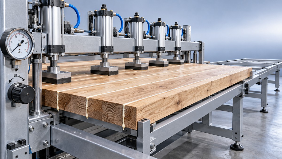
Arrange clamps according to the machine’s loading diagram, including its provisions for the panel ends. Keep pressure shoes seated squarely. If a cylinder reaches the end of its stroke before the shoe loads the panel, the indicated circuit pressure does not prove that useful clamping force is present.
Set the machine and run a controlled trial
Use representative stock, the intended adhesive spread, and the production loading pattern. A small offcut trial cannot validate a much longer panel when clamp spacing and force distribution change.
- Make mechanical adjustments with hazardous energy isolated. Follow the machine’s isolation procedure, release stored pneumatic or hydraulic pressure, and secure components that could move. Set stops, supports, and clamp positions before restoring power.
- Identify the correct control and gauge. Main supply pressure, lateral clamping pressure, and hold-down pressure may have separate regulators. Confirm the units and the circuit being adjusted.
- Enter the documented starting setting. Stay within the machine’s rated limits and the adhesive process range. On machines requiring adjustment under pressure, use the prescribed guarded setup mode and keep clear of moving parts.
- Apply adhesive consistently and load within its permitted assembly time. Follow the specified clamping sequence so boards seat without trapping a raised strip or shifting the panel against a stop.
- Observe the pressure during engagement and through the hold period. Record the loaded reading, any fluctuation, and whether the machine maintains pressure as the assembly settles.
Some regulators require a specific adjustment direction or a pressure-release cycle to establish a lower setting accurately. Follow the component and machine instructions rather than repeatedly turning the knob against a trapped downstream pressure. Never loosen fittings to release pressure.
During the trial, inspect from the designated viewing position. Stop and isolate the machine before reaching into the clamping area or repositioning material. A closed gap is useful evidence only when the panel remains correctly seated and the wood shows no local damage.
Read the panel, not just the squeeze-out
A fine, reasonably continuous adhesive bead can indicate that adhesive has reached the joint edges. It cannot prove sufficient pressure, correct spread, or a sound cured bond. Bead size changes with adhesive viscosity, application amount, wood absorption, and the time between spreading and clamping.
Heavy squeeze-out therefore does not automatically mean excessive pressure. It may reflect too much adhesive. Conversely, little squeeze-out can result from insufficient spread or delayed assembly, even when clamping force is adequate. Adjust adhesive application and pressure as separate variables.
Watch for differences along the panel. A gap confined to the middle between two clamps points toward edge geometry or force distribution. A gap beside one pressure shoe suggests poor seating, a stroke limitation, or a local mechanical issue. Increasing the whole circuit pressure can overload the areas that already have good contact.
Panel bowing during engagement calls for a different response. Examine force height, board orientation, support alignment, and hold-down timing. More vertical force can temporarily flatten a panel while leaving the cause of distortion unresolved. Inspect its shape again after release.
If pressure falls during the hold period, first establish whether the machine is designed to maintain pressure automatically or hold a trapped circuit. Settling of the wood and adhesive can affect the reading; continued unexplained loss also warrants examination of the pressure-control system. Resolve abnormal pressure behaviour before approving a production setting.
Confirm the cured joint before increasing production
Keep the trial panel clamped for the adhesive’s specified time under the actual material and shop conditions. Clamp-release time and full-cure time are different. A panel that survives unloading has not necessarily developed enough strength for aggressive machining or a meaningful bond test.
After release, inspect joint closure and flatness without forcing the panel against a table. A seam that reopens indicates an unresolved problem, such as poor fit, wood stress, insufficient bonding, or premature release. Record where it opens; its location helps distinguish a machining defect from a clamp-distribution issue.
Once the adhesive has reached the required test condition, examine sacrificial samples through the approved shop quality procedure. Samples taken near the ends and between clamping points reveal more about pressure distribution than a single convenient offcut. Assess the joint interior as well as the visible surface.
Wood failure beside the joint provides useful evidence of bond performance, but interpretation depends on wood quality and the test method. A clean adhesive-line separation requires investigation of surface preparation, spread, assembly time, pressure, and cure conditions. Do not assume pressure is responsible simply because it is the easiest control to change.
If the trial shows incomplete contact and the dry fit is sound, increase pressure by a controlled increment within the approved range and repeat the trial. Where crushing, indentation, or distortion appears, review local loading and reduce force as permitted. Change one process variable at a time so the result remains interpretable.
Save a setting that can be reproduced
Record the machine and active clamping circuit, loaded gauge reading, clamp arrangement, panel dimensions, wood species and moisture condition, adhesive, spread method, assembly time, and hold duration. Include the trial’s inspection result. A saved pressure value without these conditions is an incomplete production recipe.
Repeat validation when panel thickness or length changes, a different adhesive is introduced, clamp positions move, or repairs affect force delivery. If an established setting starts producing gaps, examine gauge accuracy, regulator stability, clamp movement, and stock preparation before raising pressure. The next adjustment should address the observed cause of the defect.
Send Your Inquiry
We welcome your cooperation and we will develop with you.