


News & Exhibitions
Latest Factory Updates, Industry Trends & Global Exhibition Information
How to reduce fuzzy edges when using an ATC CNC router for MDF
How to reduce fuzzy edges when using an ATC CNC router for MDF
Fuzzy MDF edges can turn a clean machining job into hours of sanding, rework, and finishing delays. If you operate an ATC CNC router for MDF, reducing this fiber breakout starts with matching cutter geometry, tool sharpness, and cutting parameters to the material—not simply increasing spindle speed. Stable workholding and consistent tool setup also help prevent uneven results between tool changes.
The useful question is not just “Why is this edge rough?” It is “Where does the roughness start, and what changes when it appears?” A fuzzy top lip, a hairy bottom edge, and a rough pocket wall may need different corrections. Changing everything at once usually hides the cause.
Read the edge before changing the program
Inspect a freshly cut part before sanding or sealing it. Look at the top face, bottom face, vertical wall, corners, and tool entry separately. A magnifier can help distinguish loose fibers from repeated cutter marks.
- Fuzz mainly on the top edge: check whether the cutter is lifting surface fibers, whether its downcut section actually engages the top face, and whether the cutting edge is dull.
- Fuzz mainly underneath: check bottom-face support, cut-through depth, tool geometry, and whether the part moves as it separates from the sheet.
- A rough wall through much of the thickness: investigate tool wear, runout, deflection, material quality, and cutting load.
- Roughness concentrated at corners or entry points: look at deceleration, dwell, lead-in position, and changes in engagement.
- A defect appearing after an automatic tool change: inspect the affected tool assembly and its measured offset before changing the entire cutting recipe.
Also separate fuzz from burning. Fine, raised fibers indicate incomplete shearing or fiber pullout. Darkened edges, excessive heat, and polished-looking cut surfaces suggest rubbing or recutting may also be involved. Both problems can occur together, but they are not interchangeable.
Match the cutter to the edge you need to protect
For through-cut MDF components, a compression spiral is often worth testing because its lower upcut section and upper downcut section direct cutting forces toward the panel interior. That can protect both faces. It is not automatically the right choice for every pocket, rebate, or shallow profile.
The detail operators sometimes miss is the length of the upcut section. If a shallow pass leaves the top surface within that section, the tool can still lift the top fibers. A compression cutter only provides its intended top-edge action when the downcut section reaches the top face. Check the tool drawing against the actual cutting depth, including the entry move.
For shallow pockets, a downcut tool may protect the upper rim better, but it pushes debris into the cut. Deep or narrow features can therefore become harder to evacuate. An upcut tool generally clears material upward more readily, but may leave the top edge needing additional attention. Choose according to the feature—not just the tool already sitting in the magazine.
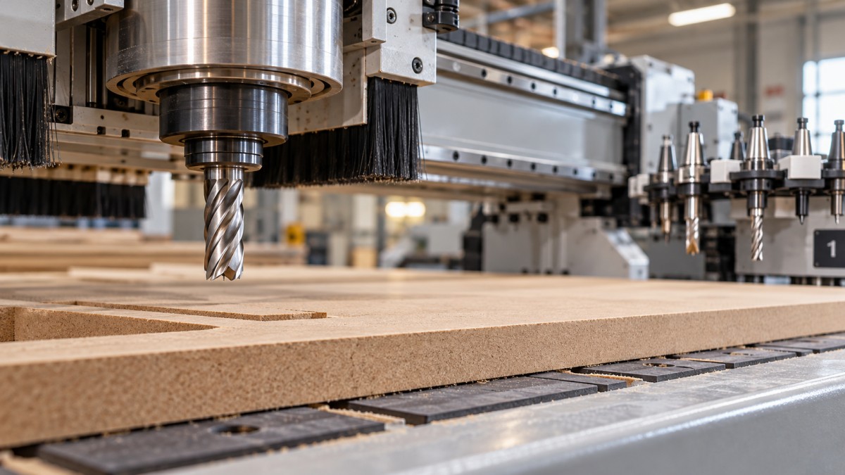
Start with a genuinely sharp, MDF-suitable cutter. Fine wear can degrade edge quality before obvious chipping appears. If a known-good replacement produces a cleaner edge with the same program and board, that is stronger evidence than repeated small speed adjustments. Keep tool projection as short as the operation safely permits; unnecessary overhang makes deflection more likely.
Adjust feed and spindle speed as a pair
Increasing spindle speed without increasing feed reduces the nominal chip load per tooth. That can make an already light cut rub more, creating heat and fine dust rather than improving the edge. Conversely, excessive feed or engagement can overload the tool and pull fibers out. The aim is a stable cutting load within the cutter supplier’s recommendations.
Nominal chip load = feed rate ÷ (spindle speed × number of cutting flutes).
For arithmetic only, a feed of 6,000 mm/min at 18,000 rpm with two flutes gives approximately 0.167 mm per tooth. This is not a recommended MDF setting: suitability depends on cutter diameter, geometry, cutting depth, engagement, and machine rigidity. Use the tool maker’s starting data, then validate it on your material.
Watch actual feed, not just programmed feed. Small radii and short segments may force the machine to slow down while the spindle maintains its speed. If straight edges are clean but inside corners are hairy or dark, examine toolpath smoothing, corner engagement, and controller behavior before lowering the feed everywhere.
Keep cutting depth and radial engagement consistent during a trial. Otherwise, a result attributed to spindle speed may actually come from a lighter cut. Listen for chatter, but judge the finished edge as well: a quiet cut is not necessarily an efficient one.
Check whether the part stays still through the final cut
An ATC CNC router for MDF cannot produce a consistent edge if the panel lifts or a small component shifts. Vacuum hold-down deserves particular attention near the end of a nested sheet, when opened kerfs increase leakage and isolated parts have less holding area.
Inspect the spoilboard for flatness, damage, and contamination. Confirm that unused vacuum zones are closed where the machine design allows, and check seals and exposed leakage paths. A vacuum reading alone does not prove that a small part is secure; effective holding also depends on its area, material permeability, and the condition of the support surface.
For vulnerable parts, consider an onion-skin strategy or tabs where the downstream process permits them. Both involve trade-offs. An onion skin needs a controlled final pass and reliable thickness references. Tabs require removal and can leave local finishing marks. Neither compensates for a badly leaking table.
Set cut-through depth from the actual panel and table condition. Too little penetration can leave bottom fibers attached; excessive penetration cuts unnecessarily into the spoilboard. Do not reach under a panel or touch a moving part to check whether it is lifting. Stop the machine and follow its isolation procedure before inspection.
When the problem follows a tool change, check the assembly
Automatic tool changing improves workflow, but each holder-and-tool assembly remains a separate source of variation. If rough edges consistently follow one tool, check its cutting edge, projection, collet condition, holder cleanliness, and length offset.
Dust or damage at a seating interface can affect repeatability. Runout can also make one flute carry more load than another, leading to uneven wear and finish. Have runout checked using the machine and tooling suppliers’ procedures rather than applying an arbitrary universal tolerance.
Follow the specified cleaning and tightening methods. Do not improvise lubrication on precision interfaces or overtighten a collet nut. After replacing or reseating a cutter, remeasure it as required by the control system and verify safe clearance before running the program.
Use a finishing pass only when it solves a defined problem
A separate finishing pass can reduce marks caused by heavy roughing engagement. Leave a deliberate, consistent allowance that lets the finishing cutter shear material rather than merely brush loose fibers. The appropriate allowance depends on the tool and operation; an extremely light pass is not always cleaner.
Cut direction is another useful test variable. Climb and conventional cutting can produce different results as tool forces interact with the wall and workholding. Compare them on a securely held sample using CAM-approved paths. Avoid reversing production contours casually when small parts are already marginally restrained.
If the roughing cut has already torn material beyond the finishing allowance, another pass will not restore the missing fibers. Fix the initial cut instead of adding cycle time to disguise it.
Keep material and dust control in the diagnosis
MDF grades and batches do not always machine identically. Density profile, internal bonding, thickness variation, and storage condition can influence edge quality. If a proven setup suddenly produces fuzz, compare another board using the same toolpath before rewriting the process.
Check extraction at the cutting point, too. Accumulated debris can be recut and interfere with machining. Inspect hoses, filters, and the dust shoe according to the equipment instructions. Do not use compressed air as a casual substitute for extraction; it can spread fine MDF dust into the work area.
A machined MDF edge will still be more porous than its factory face. Painting may require edge sealing and sanding even after a clean cut. Judge machining quality before coating, then assess the finishing process separately so that coating absorption is not mistaken for cutter damage.
Make the next trial small and traceable
Use a test piece containing a straight edge, an inside corner, and a representative pocket or through-cut. Record the board, cutter, holder, projection, spindle speed, feed, depth, and cutting direction. Change one variable, label the sample, and compare it with the previous cut before sanding. This produces a usable setup record instead of a collection of guesses.
Qingdao Zhongding Machinery Co., Ltd. brings more than 20 years of woodworking machinery experience, alongside technical support, spare parts supply, and after-sales service. When requesting support, provide edge photographs and the recorded setup details. That gives the technical team something specific to investigate rather than only a description of “poor finish.”
Once the edge meets the next operation’s requirements, save the complete recipe—not just the spindle speed. Include a reference sample and a practical tool-change criterion. The goal is a repeatable edge that needs no avoidable rework, not a perfect-looking test cut that the next shift cannot reproduce.
Send Your Inquiry
We welcome your cooperation and we will develop with you.