


News & Exhibitions
Latest Factory Updates, Industry Trends & Global Exhibition Information
What limits turning diameter on an ATC CNC router with rotary axis?
The maximum turning diameter on an ATC CNC router with rotary axis is limited by the smallest usable clearance around the rotating workpiece—not by chuck size alone. Rotary center height, bed and gantry clearance, spindle travel, toolholder geometry, and interference with the chuck or tailstock all affect the result. A blank that can rotate freely may still be impossible to machine over its full length.
Usable capacity also depends on weight, balance, support stiffness, and rotary drive performance. A machine may accommodate a large, lightweight cylindrical blank but be unsuitable for a smaller, heavy, off-center workpiece. The decisive specification is therefore a machining envelope defined for a particular blank, fixture arrangement, tooling setup, and operating condition.
“Turning diameter” can describe different capacities
On a woodworking router, “turning” generally refers to rotary-axis milling: the chuck rotates or indexes the workpiece while a powered spindle performs the cutting. This differs from conventional lathe turning, where workpiece rotation supplies the principal cutting motion. A router’s advertised turning diameter should not be interpreted as a lathe-style cutting capacity without checking its definition.
Three dimensions need to be distinguished:
- Maximum swing: the largest swept diameter that can rotate without contacting stationary machine parts in a stated configuration.
- Maximum blank size: the starting material that can be mounted and rotated, including corners, mounting offsets, and irregularities.
- Maximum machinable diameter: the diameter that the specified tool assembly can actually cut while maintaining clearance and usable axis travel.
These dimensions are not interchangeable. A quoted capacity may refer to a round blank with the spindle parked clear, rather than a workpiece being machined with a production toolholder and dust hood installed. It may also apply only to a limited section between the headstock and tailstock.
Center height sets a geometric ceiling, but only relative to actual obstructions
For a rotary unit mounted above a continuous flat bed, the basic lower-clearance relationship is:
Dlower = 2(H − C)
Here, H is the distance from the rotary centerline to the highest obstruction beneath the rotating blank, and C is the required radial clearance allowance. This gives a geometric limit, not a complete machining rating.
For example, if the centerline is 200 mm above the relevant obstruction and the selected radial allowance is 10 mm, the lower-clearance diameter is 380 mm. These are illustrative dimensions, not a recommended clearance or a machine specification. The appropriate allowance depends on setup accuracy, workpiece variation, deflection, and the manufacturer’s requirements.
The relevant obstruction might be a mounting plate, rail, fixture bolt, or support bracket rather than the tabletop. Conversely, a rotary axis installed beside the bed or over a recessed channel may allow the blank to extend below table level. In that arrangement, table height alone does not establish the diameter limit.
Clearance must also be checked above and beside the axis. A gantry crossmember, side structure, enclosure, cable carrier, or extraction component can restrict the swept envelope. Because these obstructions may change along the machine, the available diameter can vary with axial position.
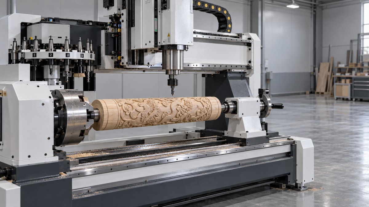
A useful clearance drawing shows a cross-section perpendicular to the rotary axis, with the blank’s swept circle and all nearby obstructions. A longitudinal view is also needed to identify restrictions near the chuck, tailstock, and ends of machine travel.
The starting blank may require much more space than the finished part
A finished diameter is not enough to establish whether the raw material will fit. For a square blank with side dimension a, centered on its geometric axis, the corner-to-corner swept diameter is:
Dswept = a√2
A 250 mm square blank therefore sweeps approximately 354 mm before any material is removed. A machine described as having a 300 mm turning diameter cannot necessarily accept that blank, even if the finished component will be less than 250 mm in diameter.
For a centered rectangular section of width b and height h, the corresponding swept diameter is √(b² + h²). Irregular blanks require the maximum distance from the actual rotation axis to any outer point, doubled. Mounting eccentricity increases that radius further.
This distinction matters for square furniture posts, laminated columns, and rough-sawn timber. Pre-rounding can reduce the required envelope and initial interrupted cutting loads, but it adds a separate operation. If production starts with square stock, machine acceptance should be based on that stock—not solely on the finished profile.
Spindle reach and toolholder clearance define what can actually be cut
A blank can clear the machine structure while leaving insufficient room for machining. With a vertical spindle positioned above a horizontal rotary axis, the cutting edge must reach the surface while the collet nut, holder, spindle nose, and non-cutting tool sections remain clear.
For top-down cutting on a cylindrical surface, the uppermost surface is one workpiece radius above the rotary centerline. The spindle must reach a valid cutting position there and retract sufficiently for safe repositioning. Both requirements must fit within the installed Z-axis range.
Published Z travel does not, by itself, establish this capability. Travel describes movement between axis limits; it does not specify the absolute location of the tool tip relative to the rotary centerline. Rotary mounting height, spindle installation position, tool length, and holder projection determine that relationship.
Deep relief introduces another constraint. A cutter may reach the bottom of a recess while its holder collides with an adjacent raised feature. Increasing tool projection can improve access, but reduces stiffness and may increase deflection, vibration, and tool breakage risk. A longer cutter is not an unrestricted remedy for inadequate clearance.
The finished geometry also matters. A three-linear-axis router with one rotary axis does not provide the tool-orientation freedom of a five-axis machine. Rotating the part can expose different surfaces, but some undercuts or end features remain inaccessible with the available spindle orientation. Diameter capacity does not guarantee complete feature access.
ATC adds clearance conditions beyond the cutting position
Automatic tool changing does not inherently increase or decrease the rotary unit’s swing. It introduces additional machine states that must remain collision-free.
A tool-change sequence can involve full Z retraction, travel to a fixed magazine, or movement near a carousel. A large blank may clear the active cutter but obstruct the spindle’s route to the magazine. The longest tool in the job can also create an interference condition that is absent with the shortest tool.
The capacity check therefore needs to include the actual tool list, holder envelopes, approach and retract moves, and tool-change path. Where a control supports an appropriate rotary-job tool-change position or clearance sequence, that sequence still needs validation for the installed configuration. A capacity claim that depends on removing the blank for tool changes does not represent an uninterrupted ATC machining cycle.
Chuck, tailstock, and supports create local restrictions
Chuck diameter primarily describes the workholding device. It does not directly define the largest workpiece diameter. Depending on its design and jaw arrangement, a chuck may grip a smaller tenon on a larger blank. That does not establish whether the chuck, spindle bearings, or drive can safely carry the resulting load.
Jaw projection matters separately. Jaws positioned outward can enlarge the rotating fixture envelope, while jaws and mounting hardware near the workpiece can obstruct the cutter. Gripping range, jaw engagement, permissible extension, and retention under cutting loads all need to be verified.
At the opposite end, the tailstock body and quill can prevent machining close to the supported end. The usable machined length may therefore be shorter than the nominal distance between centers. Changing quill extension can alter both clearance and support stiffness.
Long components may require an intermediate support or steady rest. Such a device can limit local diameter and block tool access where it contacts the workpiece. A decorative column with a large central section and narrow ends should therefore be checked as a profile along its length, rather than treated as one constant-diameter cylinder.
Weight, inertia, and stiffness can reduce practical diameter
Even when geometry permits rotation, load capacity may prevent useful machining. A maximum workpiece mass is meaningful only with its stated support arrangement, center-of-gravity position, speed, and overhang. A blank held between chuck and tailstock imposes different loads from the same blank mounted cantilevered on a faceplate.
Diameter also changes rotational inertia. For an ideal solid cylinder rotating about its centerline:
I = ½mr²
At equal mass, doubling the radius increases inertia fourfold. More drive torque is then needed for the same angular acceleration. Rapid indexing, frequent reversals, or simultaneous rotary interpolation can become restrictive even when slow rotation remains possible.
Cutting loads add a separate torque demand. A tangential cutting force Ft acting at radius r produces approximately T = Ftr at the workpiece axis. Drive selection must account for cutting torque, acceleration, transmission efficiency, and operating duty—not motor holding torque alone.
For indexed machining, a mechanical clamp may resist cutting torque if the rotary unit is designed to operate that way. During simultaneous rotation, that clamp generally cannot provide the same support while the axis moves. Capacity demonstrated in an indexed operation should not automatically be applied to continuous rotary cutting.
Balance and stiffness impose further limits. Off-center stock produces changing gravitational torque and speed-dependent imbalance forces. Long, slender timber can deflect under tool pressure, while large irregular blanks can create interrupted cuts. Reduced speed or lighter cuts may help within approved operating limits, but cannot correct inadequate workholding or structural capacity.
Make the diameter specification conditional and testable
A useful technical specification connects maximum diameter to a defined machining task. Rather than requesting one larger number, request the dimensions and ratings needed to reconstruct the envelope.
Verification should use the largest intended raw blank, the most restrictive profile features, and the actual production tooling. Collision simulation is useful only when it includes the relevant machine structures, jaws, tailstock, holders, and accessories. A simulation containing only the cutter and finished part cannot establish machine clearance.
Physical checks should follow the manufacturer’s commissioning and safety procedures, with guarded, controlled verification before cutting. Successful rotation alone is insufficient: the acceptance conditions should also address tool access, surface quality, dimensional accuracy, support stability, and the required rotary motion.
The meaningful capacity statement is therefore not simply “maximum diameter 400 mm.” It is a defined blank envelope, supported mass and length, tooling configuration, and machining cycle. That is the difference between a workpiece that merely fits and one the machine can reliably produce.
Send Your Inquiry
We welcome your cooperation and we will develop with you.