


News & Exhibitions
Latest Factory Updates, Industry Trends & Global Exhibition Information
How to set feed rates on a high-speed ATC CNC router without tear-out
How to set feed rates on a high-speed ATC CNC router without tear-out
Tear-out can turn a fast routing cycle into costly sanding, rework, or rejected parts. Setting feed rates on a high speed ATC CNC router means balancing spindle speed, cutter geometry, and chip load—not simply slowing the machine down. For operators machining plywood, MDF, or solid wood, the right settings also depend on grain direction, cutting depth, and workholding. A useful setup starts with a calculated feed, then uses controlled test cuts to find out what the material and tooling will tolerate.
The key distinction is whether the cutter is tearing unsupported fibers or struggling with the cutting load. Those problems can look similar, but they need different corrections. A slower feed may reduce overload; it will not make an upcut bit hold down a fragile top veneer.
Read the damaged edge before changing the feed
Check where the damage starts. Top-face splintering, bottom-face breakout, and a rough vertical wall should not be treated as one defect.
- Top veneer lifting: Check cutter geometry, sharpness, and whether a compression cutter’s transition is below the top surface.
- Bottom-face breakout: Check the spoilboard support, breakthrough depth, and whether the tool pushes fibers downward at the lower face.
- Periodic ridges or chatter: Investigate tool stick-out, collet condition, workholding, and cutting engagement before blaming grain.
- Burning or polished edges: Suspect rubbing, a dull edge, or chip recutting—not automatically excessive feed.
- Damage near the end of a profile: Look for a small part losing vacuum support or moving as the surrounding sheet is cut away.
On solid wood, a clean edge that becomes ragged only where the grain reverses points toward cutting direction or unsupported fibers. On MDF, fuzzy edges often justify checking tool wear and material quality alongside feed. Neither material rewards endless feed reductions with the spindle left at maximum speed.
Calculate a starting feed from chip load
Use the cutter manufacturer’s recommendations for the actual tool diameter, flute count, material, and cutting engagement. The basic relationship is:
Feed rate = spindle speed × number of cutting edges × chip load per tooth
With spindle speed in revolutions per minute and chip load in millimeters per tooth, the result is millimeters per minute. Keep units consistent; mixing an inch-based tooling chart with a metric controller creates a serious setup error.
For illustration only, suppose a tool supplier specifies 0.20 mm per tooth for a particular two-flute cutter under your intended conditions. At 18,000 rpm, the calculated feed is:
18,000 × 2 × 0.20 = 7,200 mm/min
That is an arithmetic example, not a recommended setting for every router bit. A full-width slot, a shallow finishing pass, and a deep profile create different loads. If the supplier’s chart assumes a different cutting depth or engagement, ask for guidance rather than copying its feed value unchanged.
Now consider reducing that example feed to 3,600 mm/min while keeping 18,000 rpm. The nominal chip load falls to 0.10 mm per tooth. Cutting force may decrease, but rubbing and heat can increase if the edge is no longer taking a suitable chip. “Slower” is not automatically gentler on either the tool or the surface.
If the machine cannot maintain the calculated feed on the programmed path, a lower spindle speed may help preserve chip load. Stay within the tool and spindle operating limits, including the spindle’s usable torque range. Chip load is a starting calculation, not permission to exceed mechanical limits.
Match the cutter to the face you need to protect
An upcut spiral helps evacuate chips but tends to lift fibers at the top face. A downcut spiral presses top fibers downward, which can improve the visible edge, but chip evacuation becomes more demanding in deep grooves. Poor evacuation can lead to heat and recutting even when the feed calculation looks reasonable.
Compression tooling is often useful for through-cutting veneered plywood and laminated panels because it combines opposing cutting directions. However, the upcut section at the tip must be accounted for. If a shallow first pass leaves that section cutting the top veneer, the expected protection is missing.
Check the actual upcut length on the tool drawing. Where the tool, material, and machine allow it, position the transition below the top face during the profile cut. If the required engagement is unsuitable, use a different compression geometry or a separate scoring strategy. Do not force a deep first pass just to make the cutter geometry work.
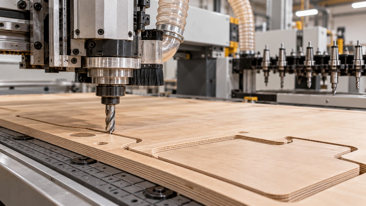
For solid wood, test the cutting direction on representative stock. Climb cutting can improve some edges on a rigid CNC setup, but grain reversal may still cause localized tear-out. Compare directions with secure workholding and an appropriate toolpath; do not assume one direction will protect every side of the part.
Run a test that separates feed problems from setup problems
Use an offcut from the production material, with the same face orientation, cutting depth, and hold-down arrangement. A shallow line across scrap tells you little about a full-depth cabinet component. Include a straight section, a corner, and an exit edge if those features appear in the job.
- Check the hardware safely. Stop the machine and follow its isolation procedure before inspecting the tool, collet, holder, or workholding. Confirm that the cutter is sharp, correctly seated, and has no unnecessary stick-out.
- Run the calculated baseline. Use a supplier-supported setting and the intended cutting engagement. Keep guards and extraction operating.
- Inspect both faces and the wall. Note where splintering occurs, whether chips clear, and whether the part stays stable. Sound alone is not a reliable diagnosis.
- Change one variable. Adjust feed within the supported range, then repeat the same feature. Keep rpm, depth, and direction unchanged for that comparison.
- Record the usable setting. Save material, tool identity, rpm, feed, depth per pass, and finish observations—not just a feed-override percentage.
Stop testing if chatter becomes severe, the workpiece moves, or chips accumulate dangerously. Those are not conditions to tune through. Correct the setup first.
If increased feed produces more breakout along an otherwise stable edge, reduce it within the recommended range and compare. If lower feed adds burning without improving splintering, reconsider cutter geometry, sharpness, or grain direction. Continuing to slow down is unlikely to solve the underlying problem.
Why the programmed feed is not always the cutting feed
A high-speed router may reach its programmed feed on a long straight edge but decelerate substantially around tight corners and short segments. With spindle speed unchanged, chip load drops during those slowdowns. That can explain why straight runs look clean while corners show heat marks.
Review the toolpath before reducing the entire job’s feed. Smoother transitions, suitable lead-ins, and fewer unnecessarily short segments may help maintain consistent motion. Changes to controller smoothing or path tolerance must preserve dimensional requirements and follow the machine supplier’s guidance.
Entry also deserves its own setting. Do not copy the horizontal cutting feed into a vertical plunge. Use the cutter’s permitted entry method and appropriate ramp or plunge parameters. Avoid placing entry and exit marks on a visible finished edge when the layout allows a better location.
Use a finishing pass when it solves a specific problem
Leaving controlled stock for a finishing pass can reduce the load on the final wall and improve consistency. It is useful when roughing creates variable engagement or visible deflection. The allowance must be sufficient for the cutter to cut rather than rub, while remaining within its supported finishing conditions.
A finishing pass will not restore veneer already torn beyond the final profile. Nor will it stabilize a loose component. On nested sheets, check vacuum zones, spoilboard condition, and the machining sequence. Small parts may need an onion skin, tabs, or another suitable retention strategy, followed by controlled removal.
Check the process after each automatic tool change
ATC repeatability does not make different tools interchangeable. Each tool needs its own spindle speed, feed, entry settings, and length data. A roughing cutter’s successful feed is not automatically suitable for the finishing tool that follows it.
If edge quality changes immediately after a tool change, check the selected tool, programmed offsets, holder seating, and contamination before rewriting the feed. A replacement cutter with a different flute count also changes chip load, even when its diameter matches the previous tool.
For technical support, provide the machine model, tool specification, material, cutting engagement, programmed settings, and photographs showing where damage occurs. Qingdao Zhongding Machinery Co., Ltd., a woodworking machinery manufacturer and exporter with more than 20 years of industry experience, provides technical support and spare-parts assistance alongside its machinery. Specific cutting details make that support more useful than a general report of “rough edges.”
Keep the proven recipe tied to the tool and material, not just the machine. When a familiar job starts tearing out, compare it against that record before changing everything. A worn cutter, a different plywood batch, or reduced vacuum support can make yesterday’s feed look wrong when the feed itself has not changed.
Send Your Inquiry
We welcome your cooperation and we will develop with you.