


News & Exhibitions
Latest Factory Updates, Industry Trends & Global Exhibition Information
What determines tongue-and-groove accuracy in solid wood flooring machines?
A flooring board can look clean as it leaves the machine and still fail at assembly. A tongue that sits slightly too high creates a step between adjacent faces. A groove that varies along the board makes installation unpredictable. When these defects repeat across a production run, the result is sorting, rework, and pressure to adjust machinery before the cause is understood.
For quality and safety teams, tongue-and-groove accuracy in solid wood working machinery for flooring depends on a chain of conditions: reference-face preparation, spindle condition, cutter geometry, feed control, setup, and wood moisture. Reliable inspection must examine that chain—not simply measure the tongue and declare the machine accurate.
Define the joint before judging the machine
There is no universal tongue-and-groove tolerance suitable for every solid wood floor. The acceptable profile depends on the product drawing, species, board thickness, installation method, and applicable flooring specification. A joint intended for one flooring construction should not automatically become the reference for another.
Before production approval, QC needs a controlled profile drawing with explicit datums. For many products, the finished walking surface is the critical reference because the tongue and groove must align adjacent top faces. However, the actual machining datum may be the underside. That distinction matters: variation in board thickness can become visible face mismatch even when the edge cutters remain correctly positioned.
The drawing and inspection plan should address:
- Tongue thickness and groove width: the dimensions governing mating clearance and assembly resistance.
- Vertical profile position: the relationship between the joint features and the specified reference face.
- Tongue projection and groove depth: sufficient engagement and the intended internal clearance without unintended bottoming.
- Shoulder geometry: the surfaces that determine joint closure and face alignment.
- Squareness and profile consistency: whether the section remains correct along the full board length.
Designed underside relief, bevels, and noncontact surfaces should also be identified. Otherwise, an inspector may reject an intentional gap or overlook a defect on a surface that actually controls the fit.
The cut is only as consistent as the board’s reference
A precision cutter cannot correct an unstable workpiece. If a board rocks on the machine bed, carries debris underneath, or has an inadequately prepared reference face, its position changes relative to the cutting circle. The finished profile may then vary despite unchanged machine settings.
Check incoming thickness variation, bow, cup, twist, and reference-face quality before adjusting the profiling heads. Longitudinal variation deserves particular attention: a short sample from the middle can pass while the leading and trailing ends remain unacceptable.
Bed plates, fences, guides, and pressure elements form part of the dimensional system. Resin deposits and localized wear can change the board’s path. A fence that is secure but incorrectly aligned may guide the timber consistently in the wrong direction.
Pressure must be enough to maintain contact with the intended datums without excessive compression or distortion. A cupped board pressed flat during cutting can spring back afterward, changing the apparent fit. This is a workpiece-control problem, not necessarily a cutter-setting error.
Spindle condition and tooling determine the cutting envelope
Runout can produce more than a rough surface
Radial runout changes the effective cutting radius; axial runout or axial movement can disturb surfaces controlled by axial cutter position. Their effect depends on the profile and cutter arrangement. Possible symptoms include incorrect dimensions, uneven knife loading, repetitive marks, and reduced tool life.
Measurement should distinguish the spindle interface from the assembled tool. Dirt on seating surfaces, damaged spacers, incorrect mounting, or an unsuitable tool assembly can introduce error even when the spindle itself is serviceable. Conversely, replacing cutters will not resolve bearing wear or spindle movement.
Use the machine manufacturer’s prescribed measurement locations, instruments, and acceptance limits. Record whether checks were made cold or under a defined operating condition; thermal behavior can otherwise make two readings appear contradictory.
A sharp edge is not necessarily the correct profile
Tool wear may gradually change joint dimensions or produce crushed fibers that interfere with assembly. Uneven wear can also create different results across the profile. After sharpening, effective diameter and profile relationships may change, depending on the tool design and grinding method.
Verify replacement and reground tools against the approved profile, including their permitted adjustment range. On multi-knife heads, projection differences can leave one knife doing disproportionate work. Tool seating, clamping torque, balance, maximum speed, and assembly compatibility must follow the relevant tooling and machine instructions.
A useful maintenance record links tool identity and sharpening history to inspection results. This helps distinguish predictable wear from an abrupt setup or mechanical fault.
Feed stability explains why a correct setup can still produce variation
Feed speed affects chip load and cutting forces, but it should not be considered separately from spindle speed, knife count, species, and cutting depth. A speed that works on straight-grained stock may produce torn grain on more difficult material. Slowing the feed indiscriminately can also create unfavorable cutting conditions rather than solve the problem.
Slipping feed rollers, inconsistent pressure, worn contact surfaces, and poor support between stations can allow the board to hesitate or shift. The resulting defect may be intermittent, making it easy to confuse with random material variation.
Inspect profiles at the leading end, middle, and trailing end. If errors concentrate at entry or exit, investigate support and the sequence of pressure engagement. If variation repeats along the board, consider feed components, vibration, and cutter-related causes—but confirm the mechanism before changing settings.
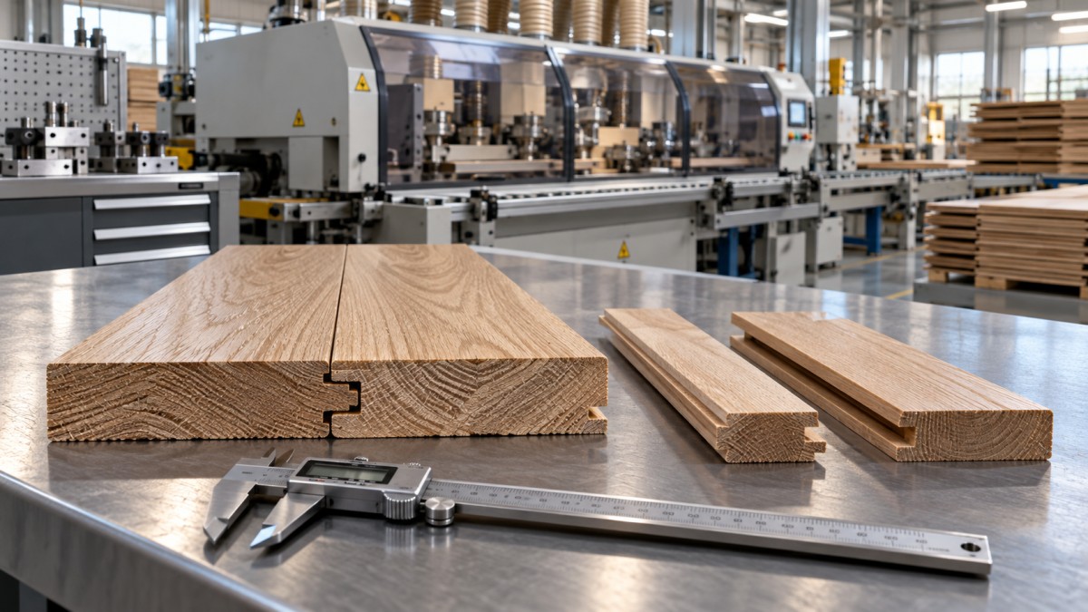
A useful inspection diagram shows the board’s reference face, tongue thickness, groove width, shoulder contact points, and measurement positions along its length. These details make discussions between operators, QC, and maintenance much more precise than descriptions such as “the joint feels tight.”
Wood moisture can imitate a machining defect
Solid wood changes dimensions as its moisture content changes, with movement influenced by species and grain orientation. A profile machined correctly under one condition may fit differently after storage. Moisture gradients and stress release can also contribute to distortion after machining.
Establish incoming and in-process moisture requirements appropriate to the product and intended service conditions. Use a suitable measurement method, applying species and temperature corrections where required. Surface readings alone may not reveal internal moisture variation in thicker stock; disputed results may require a more definitive test method.
Record the delay between machining and inspection, together with storage conditions. Comparing freshly machined boards with samples left in a different environment can lead to unnecessary machine adjustments.
A practical distinction: if dimensions change during controlled remeasurement after storage, investigate material conditioning alongside machine performance. If the defect is present immediately and tracks a particular station or setup, mechanical and process causes deserve closer attention. Neither observation alone proves the cause.
Build inspection around dimensions and actual assembly
Dimensional checks identify where the profile differs from the drawing. Assembly checks reveal whether those differences matter in the joint. Both are necessary: a pair of boards can fit because two errors compensate for each other, while a correct nominal dimension can still conceal poor shoulder geometry.
Use calibrated instruments appropriate to the feature. Calipers may be adequate for accessible dimensions, but narrow grooves, radii, and recessed shoulders can require dedicated gauges, optical measurement, or other suitable methods. Avoid forcing measuring jaws against fibers; measurement force can affect readings.
For routine production control, a practical sequence is:
- Approve first-off samples after setup, tool changes, sharpening, and relevant maintenance. Where operating temperature affects results, include verification after stabilization.
- Sample across the board length and across enough consecutive boards to expose intermittent variation.
- Check mating performance for closure, face alignment, assembly resistance, and unintended bottoming.
- Cross-match boards from different sampling times rather than testing only neighboring pieces.
- Record process conditions, including species, moisture readings, tool identity, feed settings, and adjustment history.
Reference samples are useful, but wooden masters can change with moisture and handling. Protect them, identify their status, and periodically verify them. Dedicated gauges also need documented checks and calibration appropriate to their use.
Read the defect pattern before making an adjustment
Change one controlled variable at a time where practical, then verify the result. Multiple simultaneous adjustments can temporarily improve fit while hiding the original cause.
Apply the right standards—and keep inspection safe
Product conformity, measurement control, and machinery safety are separate requirements. Depending on the market and product, references may include EN 13226 for relevant solid wood parquet elements, EN 13647 for geometrical measurement methods, or applicable national and customer specifications. Confirm the current edition and scope before adopting any reference. A product standard does not automatically establish the machine’s allowable spindle runout.
For machine safety, applicable parts of the ISO 19085 series may be relevant, depending on machine type and jurisdiction. These requirements do not replace the manufacturer’s instructions or a site-specific risk assessment.
Stop and isolate hazardous energy before accessing cutters, checking internal clearances, cleaning concealed areas, or conducting contact measurements around tooling. Prevent unexpected restart and verify isolation under the site procedure. Any energized diagnostic work requires a separately assessed, authorized method with suitable safeguards. Never bypass guards to obtain an easier measurement.
Evaluating solid wood working machinery for flooring
When assessing a machine or production line, request a trial using representative species, board dimensions, moisture conditions, and realistic feed settings. Judge consistency across boards and operating time—not a single carefully selected sample. Confirm access for safe tool changes, adjustment repeatability, maintenance requirements, and spare-parts support.
Qingdao Zhongding Machinery Co., Ltd., a woodworking machinery manufacturer and exporter with more than 20 years of industry experience, provides machinery solutions, technical support, spare parts, and after-sales service. For a flooring application, useful discussions should begin with the profile drawing, material range, inspection criteria, and required production conditions rather than a general claim of precision.
Reliable tongue-and-groove accuracy is ultimately a controlled relationship between wood, tooling, machine geometry, and measurement. The strongest production systems make that relationship visible in their records—and correct its drift before installation becomes the final inspection.
Send Your Inquiry
We welcome your cooperation and we will develop with you.