


News & Exhibitions
Latest Factory Updates, Industry Trends & Global Exhibition Information
How to prevent tear-out on an ATC CNC router for solid wood
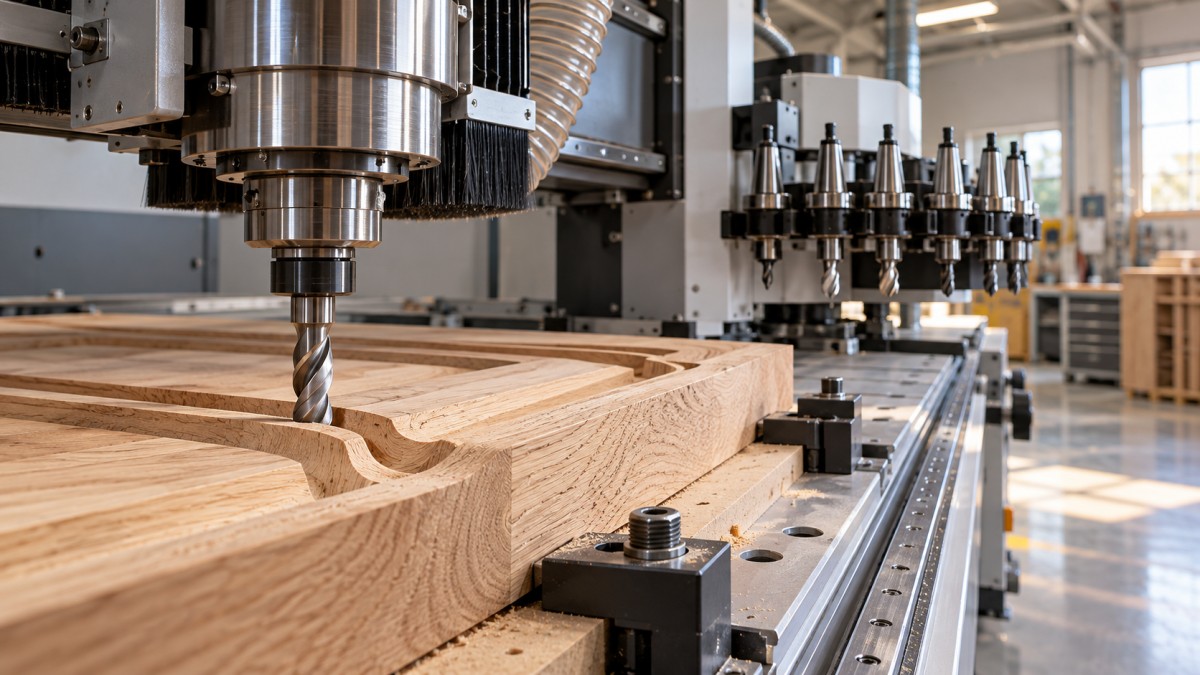
Tear-out can turn a carefully machined solid wood component into costly rework, especially around end grain, knots, and changing grain direction. On an ATC CNC router for solid wood, preventing chipped edges takes more than fitting a sharp cutter. Tool geometry, grain-aware toolpaths, cutting parameters, and secure workholding all influence whether fibers are cut cleanly or pulled away.
The most useful starting point is not simply to slow the machine down. It is to identify where the damage begins, then change the condition causing it. A chipped upper edge, a ragged underside, and a torn pocket wall may require three different corrections.
Read the damaged edge before changing the program
Inspect a rejected part before sanding it. Mark the cutting direction and grain orientation, and note whether the defect appeared during roughing or finishing. This turns an intermittent quality problem into something you can test.
Tear-out generally leaves irregular missing fibers or small craters. Chatter produces more regular marks, while burning suggests excessive rubbing, poor evacuation, or an unsuitable speed/feed combination. These problems can occur together, but treating every rough surface as tear-out often leads to unhelpful adjustments.
Match the cutter to the edge that matters
There is no single router bit that gives the best result on every solid wood operation. Choose the cutting action around the surface you need to protect.
- Upcut spirals lift chips effectively and often suit deeper pockets, but their upward action can lift fibers along the top edge.
- Downcut spirals press surface fibers downward, making them useful for top-edge quality. In deeper slots, however, they can pack chips into the cut and increase heat.
- Compression spirals combine an upcut section near the tip with a downcut section above it. Properly engaged, they can protect both faces of a through-profile.
- Shear-cut or suitable profiling tools can improve exposed-edge quality when their geometry matches the operation and wood species.
A compression bit needs particular attention. Its transition between upcut and downcut geometry must sit inside the stock, with the appropriate cutting section acting at each face. If the initial pass is shallower than the upcut section, that section may still pull fibers out of the top edge. Follow the tool supplier’s engagement guidance rather than assuming that any compression cutter automatically prevents chipping.
Do not force an excessively deep first pass just to reach the downcut section. If that exceeds the safe cutting load, use a shorter upcut-length tool, a separate top-edge scoring operation, or another suitable strategy.
Check sharpness under good lighting. A bit can still remove material while being too dull for an acceptable furniture edge. Resin buildup also changes cutting behavior; clean tools using an approved method and inspect them for damage before returning them to service.
Let grain direction influence the toolpath
Solid wood does not behave like a uniform sheet material. Grain can slope toward one face, reverse around a knot, or change direction within the same component. A full perimeter pass may therefore cut cleanly on three sides and tear badly on the fourth.
Where practical, arrange the toolpath so the cutting action presses fibers into supported material rather than lifting them away from the finished edge. The result depends on spindle rotation, travel direction, the side of the cutter in contact, and local grain orientation—not simply whether the program runs clockwise or counterclockwise.
Test climb and conventional finishing rather than assuming
Climb milling often gives cleaner edges on a rigid CNC router with secure workholding, but it is not a universal cure for solid wood tear-out. Reversing grain may respond better to a different cutting direction on selected sections. Test both directions on an offcut from the same stock, keeping tool engagement and other settings consistent.
Use CAM simulation and verify compensation when reversing a contour. Climb cutting can also increase the tendency to pull a poorly held component into the cutter; it should never substitute for adequate clamping.
Plan where the cutter leaves the wood
Breakout frequently occurs at an unsupported exit. When geometry allows, machine end-grain edges before adjacent long-grain edges so a later operation removes minor corner damage. Another option is to leave sacrificial material beyond the exit or clamp a backing block tightly against it, outside the tool’s collision envelope.
Move lead-ins and lead-outs away from visible corners. A gradual entry in waste material is usually preferable to driving directly into a finished edge.
Separate stock removal from surface finishing
Asking one pass to remove a large volume of wood and leave a presentation-quality surface creates unnecessary risk. Roughing should remove material predictably; finishing should cut a controlled allowance with stable engagement.
Leave enough radial stock for a genuine finishing cut, but not so much that the finish tool is heavily loaded. The right allowance depends on cutter diameter, species, profile depth, and machine rigidity. Too little may leave the cutter rubbing against an uneven roughed surface; too much can cause deflection and renewed tear-out.
For deep walls, consider staged roughing followed by a dedicated wall-finishing operation. A full-height finishing pass can eliminate step lines, but it also increases engaged cutting-edge length. Use it only when the tool, holder, spindle, and workholding can support the load.
A repeat pass at the same dimensions sometimes removes material left by deflection, but it is not a dependable repair for torn fibers. Once the damage extends beyond the final surface, repeating the contour cannot put the wood back.
Set feed and spindle speed together
Reducing feed alone is a common reaction to chipped edges. Sometimes it helps by reducing cutting load, but excessive slowing at unchanged spindle speed can produce rubbing, heat, and premature dulling.
Use the tool manufacturer’s recommended chip-load range as a starting point:
Chip load = feed rate ÷ (spindle speed × number of cutting flutes).
For example, a two-flute tool running at 18,000 rpm and feeding at 3,600 mm/min has a calculated chip load of 0.10 mm per tooth. This illustrates the calculation; it is not a recommended setting for every cutter or species. Depth, width of cut, tool projection, and available holding force still determine whether that setting is suitable.
Listen for changes at corners and inspect the waste. Predominantly fine dust, burning, or squealing may indicate rubbing or recutting, although some woods naturally produce finer chips. Sudden roughness during direction changes can indicate excessive engagement or unstable motion.
If cutting load is too high, reducing stepdown or radial engagement may preserve a productive chip load better than simply crawling through the cut. Confirm that extraction removes chips effectively, especially in pockets where a downcut tool can trap them.
Workholding and ATC repeatability deserve equal attention
A sharp cutter cannot leave a clean edge if the blank lifts or vibrates. Solid wood may be bowed, cupped, or rough enough to compromise a vacuum seal. Small components become particularly vulnerable as a through-cut reduces their effective holding area.
- Prepare a stable reference face and confirm that the blank sits without rocking.
- Keep the spoilboard flat and suitable for the vacuum system; isolate unused zones where applicable.
- Use fixtures, clamps, tabs, or a suitable onion-skin strategy when vacuum holding alone is insufficient.
- Place supports close enough to resist flexing without entering the cutter or holder clearance envelope.
Backing support reduces bottom-edge breakout only when it contacts the workpiece closely. A gap beneath the wood leaves fibers unsupported just when the tool breaks through. Tabs and onion skins also need a planned removal method, since careless trimming can chip an otherwise clean component.
On an ATC CNC router for solid wood, investigate tool-change consistency if quality varies unexpectedly. Following the machine’s safe isolation procedures, inspect collets, holders, and spindle interfaces for contamination or damage. Check tool projection, correct clamping, runout where appropriate, and measured tool lengths. Do not assume that every tool in the magazine is equally sharp or correctly identified in the tool library.
Qingdao Zhongding Machinery Co., Ltd. supplies woodworking machinery and technical support. When requesting troubleshooting assistance, provide the machine configuration, cutter specification, holder details, CAM settings, and clear photographs of the defect. That information is more useful than describing the surface as simply “rough.”
A short trial that produces a usable production setting
Use an offcut from the actual batch, including similar grain features where possible. A clean result on straight-grained scrap may not represent a knot-adjacent production edge.
- Establish a sound baseline. Confirm tool condition, stock stability, workholding, extraction, and tool data.
- Reproduce the difficult feature. Include the same end-grain exit, pocket wall, or curved section that failed.
- Change one factor. Compare cutting direction, finishing allowance, or speed/feed pairing without changing everything together.
- Inspect before sanding. Check both faces, corners, wall quality, and dimensional accuracy.
- Record the successful setup. Save the tool identity, species, stock thickness, engagement, feed, rpm, and holding method.
Also note stock condition. Poorly dried material, checks, loose knots, and severe grain reversal can limit the achievable finish even with a well-tuned process. Follow the material specification and assess moisture suitability rather than trying to solve every defect through programming.
The goal is a stable cutting process, not a collection of emergency finishing passes. Once the cutter supports the right fibers, the toolpath respects difficult grain, and the part remains firmly held, cleaner edges become repeatable—and sanding returns to finishing the surface rather than rescuing it.
Send Your Inquiry
We welcome your cooperation and we will develop with you.