


News & Exhibitions
Latest Factory Updates, Industry Trends & Global Exhibition Information
How feed speed affects surface finish on an MDF sanding machine
Feed speed determines how long each area of MDF remains under the abrasive. Increasing it raises throughput but reduces abrasive exposure per unit area; decreasing it increases exposure and can improve scratch refinement, provided the belt is cutting cleanly and the sanding head is correctly set. Slower feeding does not automatically produce a smoother surface: excessive exposure can increase heating, over-sanding, or localized surface damage.
The useful operating range for an MDF sanding machine is therefore not a single speed specification. It is the range that achieves the required scratch pattern, thickness tolerance, and downstream finish while remaining stable as the abrasive wears. Feed speed must be evaluated together with belt speed, grit sequence, contact geometry, sanding pressure, and incoming panel condition.
What changes when feed speed changes?
At a fixed abrasive-belt speed, slower panel movement allows more abrasive travel over each unit length of the panel. This increases the opportunity to remove high spots and refine scratches left by a previous head. Faster movement reduces that opportunity. If the abrasive cannot complete the required work during contact, residual scratches, insufficiently sanded patches, or uneven surface preparation can remain.
A useful first approximation is the contact time of a point on the panel:
Contact time = effective contact length ÷ panel feed speed
For illustration, an effective contact length of 20 mm gives approximately 0.10 seconds of contact at 12 m/min and 0.05 seconds at 24 m/min. These are calculated examples, not recommended operating settings. The effective contact length depends on roller diameter, contact-wheel hardness, platen configuration, applied load, and deformation within the contact zone.
Doubling feed speed therefore halves nominal contact time, but it does not necessarily halve stock removal or double surface roughness. Abrasive penetration, machine stiffness, belt condition, and the control method make the response nonlinear.
Feed speed also changes the relationship between panel movement and rotating machine components. A periodic disturbance from a contact roller, conveyor, or other rotating element can produce a different mark spacing when feed speed changes. This is distinct from insufficient sanding and requires a different correction.
Material removal depends on how the head is controlled
The statement “slower feed removes more material” needs qualification. On a compliant finishing head operating under approximately controlled pressure, greater exposure can increase removal until other limits intervene. On a rigid calibrating head with a fixed working gap, the set geometry strongly constrains the intended thickness reduction.
In the second case, slowing the conveyor may help the machine reach its set dimension more consistently when cutting capacity is limiting. It should not be treated as a predictable way to increase removal depth. Panel compression, abrasive deflection, machine compliance, and thickness variation can still change the result.
Conversely, increasing feed while maintaining the same nominal thickness reduction raises the material-removal demand per minute. For a constant panel width, that demand is approximately proportional to:
Panel width × thickness removed × feed speed
This explains why a setting that works on a narrow test strip may fail on a full-width panel. The wider load can produce greater motor demand, belt deflection, or incomplete cutting. Feed trials should therefore include the production width and stock allowance, not just convenient samples.
Why the same speed produces different MDF surfaces
MDF is not uniform through its thickness. Its density profile commonly includes denser face layers and a less dense core. Removing more of the face layer can expose material with different sanding and coating behavior. A surface may become more absorbent or show greater fiber disturbance even when it appears free of coarse scratches.
This makes surface preparation different from simply achieving a low roughness reading. For painted components, preserving a consistent substrate and obtaining uniform primer response can matter more than a small improvement in an isolated roughness value.
Incoming thickness variation also changes the actual sanding load. If one area engages the head more heavily than another, reducing feed may overwork the high-contact area without fully resolving the low-contact area. Head alignment, panel flatness, thickness variation, and conveyor support must be checked before attributing uneven sanding entirely to speed.
Face and edge results should not be treated as interchangeable. MDF edges expose a different density structure and may require a separate preparation process. A successful face-sanding feed setting does not establish an edge-finishing specification.
Belt speed, grit, and pressure define the usable feed range
Feed speed and abrasive-belt speed are separate variables. At a constant feed, increasing belt speed increases abrasive travel over the panel, but it also changes cutting dynamics, heat generation, dust transport, and belt behavior. Raising belt speed is not an unrestricted substitute for lowering feed; the machine and abrasive must remain within their permitted operating limits.
The grit sequence determines what each head must accomplish. A finishing belt should refine the preceding scratch pattern, not compensate for an excessive grit jump or perform substantial calibration. When feed is too high for the final head, deep scratches from the previous stage can remain beneath a finer surface texture.
Reducing feed may improve that condition, but persistent residual scratches can indicate an unsuitable sequence, insufficient finishing allowance, or a worn abrasive. Replacing a dull belt or correcting the sequence can be more effective than sacrificing line speed.
Pressure introduces another trade-off. Additional pressure can increase abrasive engagement, but it can also deepen scratches, compress the substrate, increase heating, and accelerate loading. Combining high pressure with slow feed can therefore worsen the surface rather than polish it.
Contact geometry matters as well. A hard contact roller concentrates the load and supports calibration; a compliant platen spreads contact and serves a different finishing function. Feed settings cannot be transferred between these head types solely because the abrasive grit is identical.
Read the defect before adjusting the conveyor
Surface defects provide more useful direction than a general description such as “rough finish.” Inspection under consistent raking light helps distinguish incomplete scratch removal from repeated mechanical marks or fiber disturbance.
For a suspected periodic defect, mark spacing can help diagnosis. If a disturbance occurs at frequency f, the spacing along the feed direction is approximately v/f, with feed velocity v expressed in compatible units. A controlled speed change can reveal whether the bands track a repeating machine event. It does not, by itself, identify which component is responsible.
Dust extraction must remain consistent during comparisons. Poor capture can allow dust to remain in the contact zone and promote abrasive loading. Slowing the conveyor cannot correct an extraction deficiency and may increase exposure to the resulting friction. Visible dust escape, abnormal heating, or burning odor requires investigation rather than continued speed optimization.
Establish a feed-speed window through controlled trials
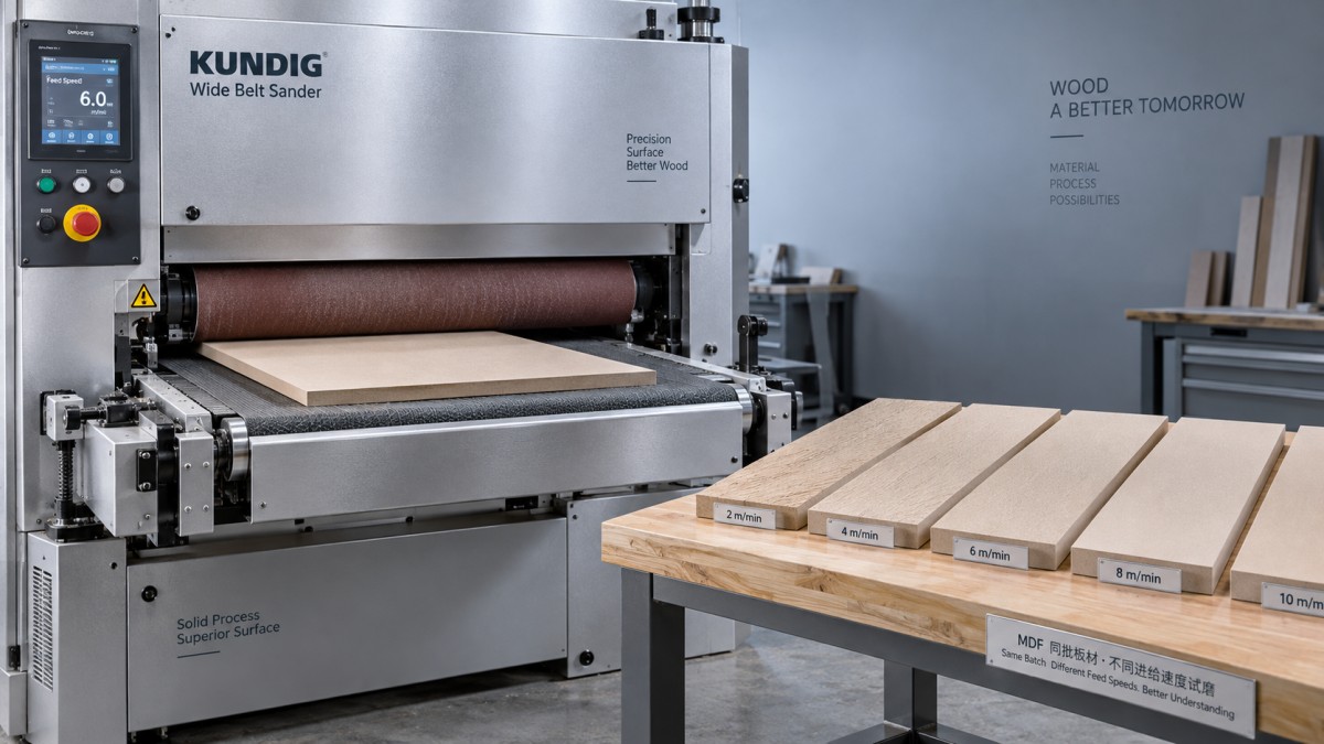
A meaningful trial holds the other influential variables steady. Use panels from a consistent material batch, document their thickness and condition, and record abrasive specification, belt condition, head settings, belt speed, and extraction settings. Begin within the machine supplier’s recommended operating range and change only feed speed during the comparison.
Use several feed settings across the relevant production range rather than comparing only one slow and one fast condition. Allow the process to stabilize, identify each sample, and record motor load or other available operating signals. A favorable surface achieved with unstable loading is not a robust production setting.
Assess thickness before and after sanding at repeatable locations across the width and along the panel. This separates surface improvement from unintended extra removal. Include leading and trailing areas, where transient engagement can differ from the central portion.
Upstream preparation should also be controlled. A panel-cutting machine such as the BEAM SAW MJ6226 performs a different operation from sanding; its cutting-feed specification cannot establish a sanding-feed setting. For a sanding trial, consistent panel dimensions and supported entry and exit conditions are the relevant connection.
Repeat promising settings with an abrasive that has reached a representative working condition. A new belt may provide enough cutting capacity to conceal a marginal process window. The selected feed should remain acceptable across a defined usable belt-life interval, not only immediately after replacement.
Define surface acceptance beyond one roughness number
There is no universal feed-speed value that guarantees a paint-ready MDF surface. Acceptance needs to describe the actual outcome: residual scratch visibility, thickness variation, surface defects, and performance under the intended coating or bonding process.
Instrumental roughness measurements can support comparison, but the method must be repeatable. State the instrument type, filtering and evaluation settings, measurement direction, and sampling locations. Measurements along and across the dominant scratch direction may differ. Changing the measurement setup between samples can obscure the effect of feed speed.
Ra alone is insufficient because an average can underrepresent isolated deep scratches or localized defects. Supplement it with profile examination, an appropriate peak-to-valley parameter where relevant, and controlled visual inspection. Do not assign a universal numerical acceptance limit without a validated connection to the downstream finish.
For painted MDF, apply the intended primer and finishing sequence to trial panels. Inspect for scratch telegraphing, uneven absorption, and fiber raising after coating and drying. A surface that looks satisfactory immediately after sanding can behave differently once wetted by the coating system.
The defensible production setting is a feed-speed range tied to a defined panel specification, abrasive sequence, head configuration, and acceptance method. Its upper boundary is where scratch removal, dimensional consistency, or machine loading becomes unacceptable; its lower boundary is where additional exposure stops helping or introduces heating and overworking. Operating with margin inside those boundaries is more reliable than treating either maximum conveyor speed or minimum measured roughness as the sole target.
Send Your Inquiry
We welcome your cooperation and we will develop with you.