


News & Exhibitions
Latest Factory Updates, Industry Trends & Global Exhibition Information
How Automatic Woodworking Machinery Synchronizes Feeding and Panel Transfer
How Automatic Woodworking Machinery Synchronizes Feeding and Panel Transfer
A woodworking line is only as efficient as its ability to move each panel into position at the right moment. In automatic woodworking machinery, synchronized feeding and panel transfer depend on coordinated drives, position sensors, and control logic that align material flow with processing cycles. A conveyor can run smoothly in isolation and still cause trouble when connected to an edge bander, drilling machine, or panel return system.
The problem is rarely just speed. A panel must arrive with the correct spacing, orientation, and support, while the receiving machine is ready to accept it. Evaluating that coordination means looking beyond rated feed rates to understand what happens during acceleration, handover, downstream delays, and restart after a fault.
Synchronization Starts with Permission, Not Motion
Consider a feeder supplying panels to an edge bander. The feeder may have a panel waiting at its discharge position, but that does not mean it should release it. The receiving machine must be running, its infeed area must be clear, and the required gap behind the previous panel must be available. Depending on the design, workpiece identification and recipe selection may also need confirmation.
This is normally managed through an exchange of control signals, often called a handshake. One machine reports that a panel is available; the next reports that it can receive it. The controller permits transfer only when the relevant conditions agree. Completion must then be confirmed so that neither machine continues operating on an outdated assumption.
A useful sequence distinguishes between “ready to receive,” “transfer authorized,” “transfer in progress,” and “transfer complete.” These are functional states, not necessarily separate wires. They may be exchanged through discrete inputs and outputs or an industrial communication network.
The important question is what each signal actually means. “Ready” should not merely mean that power is on. An interface specification should define signal ownership, timing, timeout behavior, and how permissions are withdrawn if conditions change during transfer.
Keeping Drive Movement Aligned with the Actual Panel
Variable-frequency drives can provide suitable speed control for many conveyor sections. Servo drives become useful where the process requires controlled indexing, repeatable positioning, or closely coordinated acceleration. However, a servo motor does not automatically make the panel position accurate: it controls the axis, while the panel may still slip against a belt or roller.
Some systems use a common speed reference across connected conveyors. Others use encoder feedback, electronic gearing, or motion profiles to coordinate selected axes. The appropriate arrangement depends on whether the line needs continuous flow, intermittent feeding, or precise registration at a processing station.
At a handover, matching commanded speeds is only part of the task. Roller diameter, belt wear, drive scaling, and surface friction influence actual panel velocity. If the receiving conveyor pulls faster while the upstream section still grips the board, the panel may scuff or rotate. If it runs slower, the panel may be compressed between transport sections or lose its intended spacing.
Where two sections must grip the same panel, their velocity profiles and release timing need to be compatible. Some designs deliberately use controlled speed differences to separate panels, but that requires suitable contact surfaces and a defined operating window—not an accidental mismatch.
Acceleration deserves equal attention. An aggressive ramp may work with one board surface but cause another to slide. Hold-down pressure can improve traction, yet excessive pressure may mark sensitive finishes. The setting is a compromise between reliable transport and acceptable surface contact.
Sensors Close the Gap Between Calculation and Reality
A controller can estimate panel travel from conveyor speed and elapsed time. That estimate becomes less dependable when panels slip, movement pauses, or an operator removes a workpiece. Physical detection at critical transfer points provides confirmation that the expected movement actually occurred.
Photoelectric sensors commonly detect leading and trailing edges. Encoders provide travel information, while additional sensors may confirm lateral position, lift-table height, or the presence of a panel against a stop. No single sensing method answers every question. A motor encoder confirms shaft rotation; it does not independently prove that the panel moved the same distance.
Sensor selection also depends on the material. Dark surfaces, glossy laminates, dust accumulation, and irregular edges can affect detection, depending on the sensor technology and installation. A sensor that performs well with unfinished board should not be assumed suitable for every decorative finish without testing.
Typical confirmation points include the feeder exit, receiving conveyor entrance, and registration position. The controller should check that each transition occurs within an expected window. If a panel leaves one sensor but never reaches the next, continuing to feed more panels is usually the wrong response.
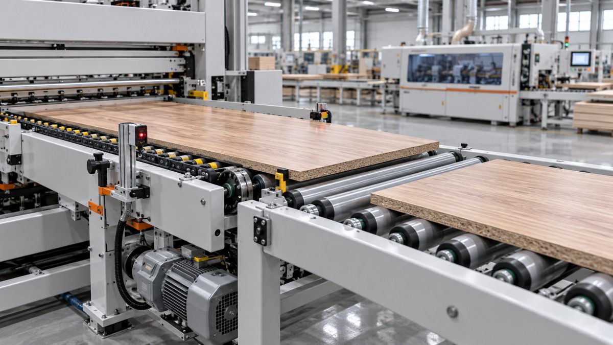
A useful transfer-layout drawing should show sensor positions, transport direction, independently controlled conveyor zones, and the handover boundary. This often exposes integration gaps more clearly than a machine-by-machine equipment list.
Spacing and Buffers Determine Sustainable Throughput
Maximum conveyor speed is not the same as line capacity. For a continuous stream of equal-length panels, a simplified transport relationship is:
Panels per minute = conveyor speed ÷ (panel length in the travel direction + inter-panel gap)
With speed expressed in metres per minute, length and gap must both be in metres. This relationship describes transport spacing only. It does not account for indexing, processing time, turning, loading delays, or machine availability. Mixed panel lengths make a single headline capacity figure even less representative.
The minimum gap is also process-dependent. A downstream machine may need space for its detection sequence, clamping cycle, or mechanism reset. Reducing the gap to increase output can therefore make feeding less reliable without increasing completed production.
Buffers help absorb short differences between station cycles. A drilling machine may stop a panel for processing while an upstream section continues preparing the next one. Independently controlled zones can hold panels without pushing them into occupied positions.
But buffers cannot solve a permanent capacity mismatch. If the receiving process is consistently slower, the buffer eventually fills. Its value lies in absorbing temporary variation. Usable capacity must be checked against actual panel lengths, stopping distances, and any restrictions on contact between workpieces.
Mechanical Handover Can Defeat Good Control Logic
A transfer can be correctly timed and still fail mechanically. Short panels may lose support across a conveyor gap. Thin panels may deflect as they enter the next section. Long panels may skew if one side experiences more resistance than the other.
Check the transfer gap, working height, roller pitch, guide arrangement, and hold-down position against the full workpiece range. The shortest permitted panel is particularly important: it must remain adequately supported and driven throughout the handover, not just when stationary on either conveyor.
Right-angle transfers introduce another sequence. The incoming panel generally needs to reach a defined position before cross-transfer belts, chains, or lifting elements take over. The original transport must release it appropriately, and the receiving path must be clear. Trying to overlap these actions without sufficient positional control can turn a small alignment error into a jam.
Surface protection belongs in the same review. Dust and chips trapped at contact points can scratch decorative panels even when the motion sequence is correct. Cleaning access, belt condition, and guide materials should be treated as operating requirements rather than minor maintenance details.
Fault Recovery Is Part of Synchronization
A convincing demonstration should include interruption and recovery, not only uninterrupted running. Stop the downstream machine while a panel is waiting. Check how the upstream section responds. Then examine what happens when a panel is stopped across the handover boundary.
After a fault, the controller needs a reliable account of panel locations. Simply clearing an alarm may leave software tracking inconsistent with the physical line. Recovery may require sensor checks, controlled repositioning, or an operator confirmation under a defined procedure. Automatic restart should not rely on a guessed workpiece position.
Process coordination must also be distinguished from safety-related control. A normal “ready” signal is not automatically a safety function. Guard interlocking, emergency stops, and prevention of unexpected motion require a risk-assessed design. The ISO 19085 series addresses woodworking machinery safety, while ISO 13849-1 addresses safety-related parts of control systems; applicable parts, editions, and local requirements need project-specific review.
What to Verify Before Accepting an Integrated Line
Acceptance testing should use a representative production mix, including workpieces near the agreed operating limits. Testing only a convenient medium-sized panel leaves too much unexamined. The test plan should establish:
- Workpiece limits: dimensions, mass, surface finish, and permitted condition.
- Positioning criteria: longitudinal registration, lateral alignment, and acceptable skew.
- Production conditions: panel sequence, required gaps, processing recipes, and buffer behavior.
- Recovery behavior: blocked discharge, transfer timeout, interrupted movement, and restart procedure.
- Support documentation: interface signals, drive settings, sensor details, backups, and troubleshooting instructions.
Qingdao Zhongding Machinery Co., Ltd. brings more than 20 years of woodworking machinery manufacturing and export experience to equipment and complete-solution discussions. For an integrated project, that discussion should extend beyond machine selection to transfer responsibilities, commissioning scope, spare parts, and long-term technical support. Specific control functions still need confirmation against the proposed configuration.
The practical test of automatic woodworking machinery is not whether every conveyor starts together. It is whether each panel remains accounted for, supported, correctly spaced, and recoverable when production stops behaving like the demonstration. Before acceptance, ask the supplier to show that sequence with your workpieces—including the interruption.
Send Your Inquiry
We welcome your cooperation and we will develop with you.