


News & Exhibitions
Latest Factory Updates, Industry Trends & Global Exhibition Information
Machining MDF Without Chipping: Tooling, Feed Rates, and Workpiece Support
Chipped MDF edges can turn a routine cabinet-panel job into extra sanding, damaged coatings, and rejected parts. The most effective correction is usually a combination of sharp, correctly oriented tooling, a suitable chip load, and support directly beneath the cut. Simply reducing the feed rate can make matters worse if the cutter starts rubbing instead of cutting.
Before changing settings on woodworking machinery for MDF, identify where the damage occurs: the top face, bottom face, corners, or entire machined edge. That location helps distinguish a tooling problem from poor hold-down, excessive engagement, or an unsuitable toolpath. Make adjustments on an offcut of the same board, including the same surface finish, rather than risking another finished component.
Read the damaged edge before adjusting the machine
MDF does not splinter along grain like solid wood, but its compressed fibers can still break away at an unsupported cutting boundary. Its faces are generally denser than its core. A cutter may therefore leave a reasonably smooth face while producing a fuzzy or torn edge deeper in the panel. Melamine, veneer, and other surface layers introduce a separate failure point: the coating can fracture even when the MDF underneath looks acceptable.
Damage that increases as the sheet is processed may indicate tool wear or accumulating dust. Damage confined to one area of the table points more strongly toward local support, spoilboard flatness, or vacuum leakage. These patterns are more useful than judging a single rough edge in isolation.
Match the cutting geometry to the face you need to protect
Upcut, downcut, and compression router bits
An upcut spiral lifts fibers and chips toward the spindle. It generally clears enclosed grooves effectively, but that upward action can disturb the top edge. It is useful where chip evacuation or bottom-face quality takes priority, provided the workpiece is held securely.
A downcut spiral presses fibers toward the panel, helping preserve the top boundary. The trade-off is downward chip movement. In deep slots, chips can pack around the tool, increasing heat and cutting resistance. A downcut bit is not automatically the best choice for deep machining or for a bottom face that must remain clean.
A compression bit combines an upcut section near the tip with downcut geometry above it. For through-cutting, its transition must sit inside the panel so the lower section protects the bottom and the upper section protects the top. A shallow first pass with a conventional compression bit may leave its upcut section cutting the top face, causing the very chipping it was selected to prevent.
Check the manufacturer’s geometry drawing, especially the upcut length, rather than relying on the word “compression.” Thin panels and shallow features may require a short-upcut design or a different machining strategy. Do not force a full-depth cut simply to engage the geometry if the tool or machine cannot support that engagement.
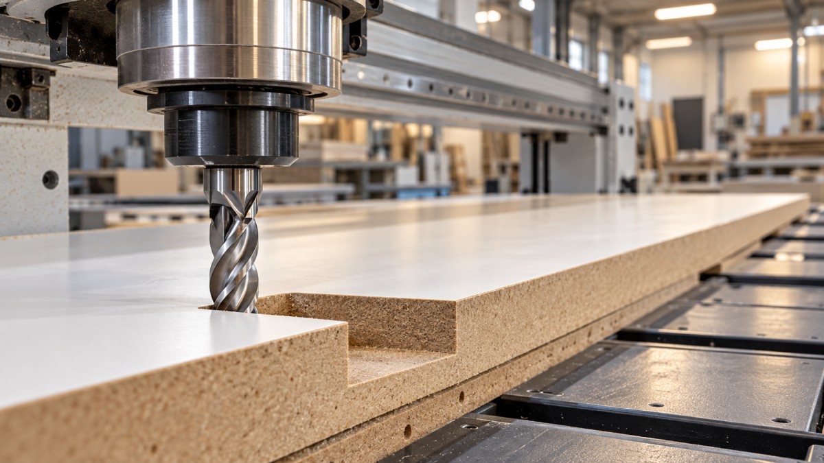
Sharpness and rigidity matter as much as spiral direction
MDF is abrasive, so a cutter can look intact while its edge has become rounded. Carbide tooling is commonly used; diamond tooling may be appropriate for repetitive production where the application and economics justify it. Neither material compensates for an unsuitable geometry or unstable setup.
With the machine isolated, inspect for chipped edges and buildup. Clean the collet and mating surfaces, check tool insertion against the holder manufacturer’s instructions, and minimize unnecessary stick-out. Runout makes cutting edges carry unequal loads and can produce poor finish even when the programmed chip load appears reasonable.
Set feed rate through chip load, not guesswork
There is no universal MDF feed rate. Tool diameter, flute count, cutting depth, radial engagement, spindle capability, and panel construction all change the workable range. Start with the tool supplier’s MDF recommendations for the actual operation, then test within the machine’s limits.
Feed rate = spindle speed × number of flutes × chip load per tooth.
For example, if a supplier recommends a chip load of 0.15 mm per tooth for a particular two-flute cutter and operation, running at 18,000 rpm gives a calculated feed of 5,400 mm/min. This is a calculation example, not a general MDF setting. The assumed chip load must first be suitable for the tool, cutting engagement, and machine.
Reducing feed while leaving spindle speed unchanged reduces chip load. Below a useful cutting range, the edge rubs more than it cuts, generating heat and accelerating wear. Conversely, excessive chip load can overload the tool, deflect it, or move the workpiece. A rough edge alone does not tell you which condition is present.
- Heat or scorching: check for a dull edge, chip recutting, and insufficient feed relative to rpm.
- Chatter or visible deflection: check rigidity and hold-down, then reduce engagement or adjust cutting parameters.
- Good straight edges but damaged corners: check actual feed during machine deceleration and engagement through the turn.
MDF naturally produces fine dust, so particle size alone is not a reliable chip-load gauge. Compare edge quality, sound, spindle load where available, and signs of heat. Change one variable at a time and record the result. When a machine cannot maintain the calculated feed, lowering rpm within the approved operating range may be more appropriate than allowing prolonged rubbing.
Support the cut boundary, not just the sheet
A panel can feel secure while the final strip or small component vibrates as it separates. Support must remain effective throughout the toolpath, particularly near breakthrough and the last section of a profile.
On a CNC vacuum table, check that the spoilboard is flat, clean, and suitable for the hold-down system. Isolate unused zones and address leakage according to the machine instructions. Dust trapped beneath a panel creates uneven support; open cut paths can also reduce holding force as machining progresses. A large sheet staying still does not prove that every small nested part will remain secure.
A sacrificial backing board supports the underside during through-cutting. Set the cut depth to separate the panel with only the necessary penetration into the backing, allowing for measured thickness variation and table flatness. Excessive penetration increases unnecessary engagement and damages the spoilboard faster.
Small parts may need approved fixtures, tabs, or an onion-skin strategy that leaves a thin layer until the final operation. Onion skinning only helps if the last pass still has adequate retention. Tabs also require a removal method that will not tear the finished edge. Keep clamps, screws, and fixtures outside every cutting and rapid-travel path.
Use toolpaths that avoid tearing the last fibers away
Cutting direction changes how the edge loads the material. On a rigid CNC machine with secure workholding, climb milling often gives a cleaner routed boundary, but the result depends on geometry and material. Compare directions on scrap rather than treating either as universally superior. Do not transfer CNC climb-milling practice to handheld or manually fed routing: self-feeding forces can cause loss of control. Follow the machine’s prescribed feed direction.
Lead-ins and lead-outs can move entry marks away from a finished boundary. Place them where the part remains supported and the tool can engage without plunging against a visible edge. For pockets or deep slots, use an approved ramping or entry method suited to the cutter instead of assuming every router bit can plunge vertically.
A roughing pass followed by a finishing pass can reduce edge loading, but the finishing allowance must be large enough for the tool to cut rather than rub. It must also stay within the cutter’s recommendations. Multiple shallow passes are not always cleaner: they may repeatedly expose a fragile coating to unfavorable cutting action, especially with incorrectly engaged compression geometry.
For panel saws and drilling, focus on the exit face
Routing settings do not transfer directly to sawing. On a panel saw, use a sharp blade specified for MDF or the relevant coated panel, with tooth geometry and count appropriate to the machine and cut. Where a scoring unit is fitted, its alignment and scoring width must match the main blade setup. A misaligned scorer can leave a step rather than a clean boundary.
Inspect blade condition, alignment, support, and feed consistency before assuming blade speed is the cause. Set blade projection according to the machine and blade instructions. Keep guards and extraction in place; never attempt to steady a narrow offcut by hand near the blade.
For through-holes, clamp the panel against clean sacrificial backing and use tooling intended for panel drilling. Unsupported breakthrough can break out the lower face even when the hole entrance is clean. Reduce breakthrough stress using the drilling method permitted by the equipment, without dwelling long enough to burn the bore.
Validate the setup before restarting the batch
- Make the machine safe for inspection. Follow isolation procedures before checking cutters, collets, blades, or fixtures.
- Prepare a representative offcut. Match the panel thickness, coating, and support used in production.
- Test the troublesome feature. Include a corner, slot, or small profile if that is where damage appears.
- Inspect both faces and the full edge. Check for breakout, fuzzing, burning, coating lift, and movement marks.
- Record the workable setup. Note tool identity, rpm, feed, pass depths, cutting direction, and hold-down arrangement.
Keep effective dust extraction operating during tests and production. MDF dust presents an inhalation hazard, and accumulated dust also interferes with chip evacuation and support. Use enclosure and respiratory protection as required by the material safety information and workplace assessment; do not clear the table by blowing dust into the air.
If chipping persists with a verified sharp tool, suitable parameters, and stable support, investigate spindle runout, holder condition, machine alignment, and panel quality. Stop immediately for unexpected vibration, abnormal spindle noise, or workpiece movement. These are equipment or retention faults to resolve before further feed-rate experiments, not finish defects to hide with sanding.
Send Your Inquiry
We welcome your cooperation and we will develop with you.