


News & Exhibitions
Latest Factory Updates, Industry Trends & Global Exhibition Information
Woodworking Production Line Planning: Balancing Cutting, Edging, and Drilling
A fast panel saw cannot prevent missed deadlines when edge banding and drilling cannot absorb its output. A balanced woodworking production line is sized around the workload required to complete a saleable product—not around matching the advertised speeds of individual machines. The practical objective is reliable output of complete component sets, with controlled work-in-progress between operations.
That requires more than comparing panels per hour. Cutting capacity depends on sheet layouts and handling; edging depends on the number and length of edges, material changes, and return passes; drilling depends on hole patterns, machining faces, and positioning. Effective woodworking production line solutions translate these different workloads into a common production schedule before equipment quantities and automation levels are selected.
Define the production mix before calculating capacity
A target such as “100 cabinets per shift” is insufficient for line planning. A cabinet with adjustable shelves, drawers, and exposed ends creates a different machining load from a simple carcass. Even when two orders contain the same number of panels, their edging and drilling requirements can differ substantially.
The planning baseline should therefore be a representative bill of materials and routing file. Each component needs dimensions, substrate, thickness, grain direction where relevant, edge treatment, drilling pattern, and required quantity. Parts that bypass an operation must remain visible in the calculation; assuming every panel follows the same route can lead to unnecessary equipment investment.
Group components by the characteristics that drive machine workload rather than by finished product name alone:
- At cutting: sheet format, thickness, material type, nesting or saw pattern, and minimum part dimensions.
- At edging: number of treated sides, edge length, banding material, adhesive system, profile, and appearance requirements.
- At drilling: hole count and arrangement, machining faces, grooves, hardware recesses, and clamping requirements.
Use more than one demand scenario. An average mix helps establish baseline capacity, while a drilling-heavy or edging-heavy mix reveals whether the proposed line can meet delivery commitments without relying on overtime. These scenarios should come from intended orders or credible sales plans, not an arbitrary percentage added to every machine specification.
Convert machine performance into comparable workload
The most useful common measure is required machine time per shift. For each process, calculate the workload from the component mix, then compare it with the time genuinely available for production.
Required process time = total quantity-dependent processing time + scheduled setup and changeover time.
Quantity-dependent time must include the activities that occupy the machine or prevent the next part from entering: loading, positioning, machining, unloading, and any required return handling. If a measured cycle already includes these activities, do not add them again. Likewise, distinguish scheduled breaks, setup time, unplanned downtime, and quality losses so that the same loss is not deducted twice.
Consider an illustrative shift with 420 minutes available after planned breaks, but before process-specific setups. The following figures are planning assumptions, not equipment benchmarks.
In this example, edging is the capacity constraint even though all three processes nominally fit within the shift. Its 35-minute margin must absorb interruptions and workload variation. Increasing cutting speed would not increase completed output unless the edging constraint were relieved; it would mainly increase the queue ahead of it.
The calculation also needs to identify shared resources. If one person loads the saw and transfers panels to edging, independently calculated machine capacities may not be simultaneously achievable. The same problem occurs when machines share a return conveyor, lifting device, or limited staging area.
Resolve the different capacity drivers at each operation
Cutting: sheet output is not component output
A panel saw’s cutting speed does not directly establish how many usable components reach the next process. Sheet loading, stack height, cutting patterns, sorting, labeling, and offcut removal all affect release rate. Stack cutting can produce a large batch quickly, but it may also release identical parts faster than downstream operations need them.
A nesting router changes the balance. Where appropriate, it can combine cutting with some face drilling or grooving, reducing the load on a downstream drilling machine. However, tool changes, hold-down performance, small-part stability, and unloading must be included in the nesting cycle. Work transferred upstream is not eliminated; its time and quality requirements move to another resource.
The choice between sawing and nesting should therefore be evaluated against the complete routing. A higher cutting cost per panel can still be justified if it removes a constrained downstream operation or reduces handling enough to improve completed-set output.
Edging: count passes, not just panels
A single-sided edge bander may require several passes for one component. Its feed speed describes travel through the machine, not the total time needed to finish all required edges. Part spacing, minimum dimensions, rotation, return travel, and operator access can determine effective throughput.
Build edging workload from the actual pass sequence. Separate long runs using one edge specification from short batches requiring changes in tape, thickness, adhesive, or finishing settings. A line sized using only long, uninterrupted runs may fall short when the order mix contains many finishes.
Before adding a second machine, identify what consumes the constrained time. Improved return handling, material preparation, or setup sequencing may release capacity. These measures will not solve a genuine machining-capacity shortage, but they can prevent investment in equipment that remains limited by the same handling arrangement.
Drilling: identical panel sizes can hide unequal cycles
Drilling time depends on the machining program, not simply panel area. A side panel with shelf-pin rows, hinge-related features, grooves, and edge holes can require much more time than a similarly sized shelf.
Confirm whether the proposed machine can process all required faces and features in one loading. Repositioning, manual flipping, additional clamping, or a separate horizontal boring operation changes both cycle time and staffing requirements. Program retrieval and part orientation must also be included when the line handles mixed components.
Use representative part programs for capacity validation. An average calculated from simple components can conceal the drilling-heavy jobs that determine delivery performance.
Use buffers to protect flow, not conceal imbalance
Directly connecting every machine can reduce handling, but it also allows one interruption to stop adjacent operations. Limited buffers between cutting, edging, and drilling can decouple short disturbances without turning the factory into a storage area.
A practical starting point is to express each buffer in minutes of downstream consumption rather than in an arbitrary number of pallets. If edging consumes two panels per minute under a defined product mix, a 20-minute interruption upstream would require 40 correctly sequenced panels to keep it supplied. This is an illustrative calculation; actual coverage depends on component mix, rack capacity, and handling constraints.
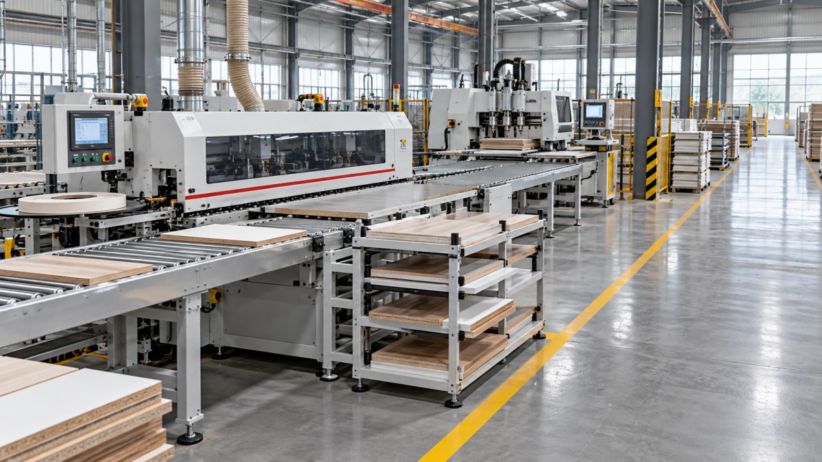
The buffer must contain the right work. Forty panels from an order not scheduled for edging do not protect the next scheduled job. Separate lanes by production status or sequence, make queue limits visible, and define what happens when a lane is full. Otherwise, cutting can continue releasing material while the constraint becomes buried in unsorted work.
Protect space after the constrained operation as well. An edge bander can lose productive time if finished panels cannot be unloaded because drilling’s input area is full. Buffer planning therefore needs both starvation and blocking analysis.
Buffers cannot correct a persistent capacity deficit. If edging requires more time than the shift provides every day, additional racks merely delay the point at which the imbalance becomes unavoidable.
Release work according to complete-set delivery
Cutting optimization and assembly priorities can conflict. Grouping sheets by material may improve yield and reduce setups, yet leave downstream areas holding incomplete cabinet sets. Conversely, releasing every order as a separate small batch can increase material changes and reduce effective machine capacity.
A workable release policy defines how much work may enter the line and how orders may be grouped. Batch compatible materials and finishes where this saves meaningful setup time, but preserve component identity and delivery sequence. Labels or equivalent identification should connect each part to its routing, program, orientation, and order.
The scheduling rule should also cover exceptions. A damaged panel requiring recutting needs a controlled route back through edging and drilling; otherwise, a nearly complete order can wait behind newly released batches. Reserve recovery capacity based on measured loss patterns once operating data become available, rather than assuming all nominal output will become good parts.
Track completed sets alongside individual machine counts. High panel output is not a useful achievement if assembly is waiting for a small number of missing sides or shelves.
Keep solid-wood preparation on its own routing
For production combining panel carcasses with solid-wood components, thickness preparation belongs in the routing calculation but should not be confused with panel sizing. A Double Sided Planer machines upper and lower wood surfaces in one pass and supports thickness control before subsequent operations. It does not replace panel cutting, edge banding, or drilling.
Its workload should be evaluated for the solid-wood branch only, accounting for incoming stock, required removal, allowable dimensions, feed conditions, and subsequent machining allowances. Adding this preparation stage to the main panel-flow calculation when those panels do not require it would distort both capacity and floor-space planning.
Validate the line as an operating system before acceptance
Layout approval should include material movement, not just machine footprints. Allow for infeed and outfeed lengths, panel turning, maintenance access, consumable replenishment, offcut handling, and safe separation of people from transfer equipment. Dust extraction, compressed air, electrical supply, and network connections must support simultaneous operation under the intended load.
Supplier demonstrations should use representative component files and materials, including demanding edge specifications and drilling patterns. Record elapsed time from material availability to correctly completed parts—not only spindle-running time. Where machines exchange production data, verify label readability, program selection, revision control, and recovery after an interrupted job.
Acceptance criteria should distinguish individual equipment capability from integrated line performance. Agree the product mix, staffing, quality requirements, setup allowance, test duration, and treatment of interruptions before testing. A short demonstration using one easy component cannot establish sustained mixed-order capacity.
Investment decisions should then follow the verified constraint. If additional cutting capacity produces no increase in accepted, complete component sets, it is not the priority. The stronger plan is the one that delivers the required mix within the available shift, with explicit allowances for variation and a defined response when cutting, edging, or drilling falls behind.
Send Your Inquiry
We welcome your cooperation and we will develop with you.