


News & Exhibitions
Latest Factory Updates, Industry Trends & Global Exhibition Information
Choosing vacuum hold-down for small parts on an ATC CNC router for MDF
Choose vacuum hold-down for small MDF parts by evaluating the smallest component at its final separation cut. A full sheet can remain firmly seated while a nearly finished part slides, rotates, or lifts. For an ATC CNC router for MDF, the selection therefore starts with effective holding area, leakage through the material and spoilboard, and the forces generated by the actual toolpath. Pump motor power alone cannot establish whether the finished component will stay secure.
A zoned, full-sheet vacuum table suits nested production when enough material remains connected during cutting. As components become smaller, narrower, or more heavily machined, dedicated gasketed fixtures, tabs, or a controlled onion-skin pass become more relevant. The right arrangement must retain the part through the least favorable cutting condition, including the moment its perimeter becomes fully open.
Start with the area that remains under vacuum
The basic relationship is straightforward: pressure difference multiplied by effective area produces the theoretical force pressing the part against its support. That force acts perpendicular to the table. Resistance to sideways cutting forces also depends on friction at the contact surface, while resistance to rotation depends on the shape and distribution of the supported area.
Effective area deserves particular attention. On a gasketed fixture, it is the evacuated area enclosed by the seal, excluding areas that are not connected to vacuum. On a porous spoilboard, the pressure beneath the workpiece is less uniform and changes as air enters through the board, exposed surfaces, and newly opened kerfs. The component’s outside dimensions are therefore an unreliable substitute for effective holding area.
A long, narrow strip presents a different problem from a compact part with a similar footprint. A cutting force acting near the end of the strip creates leverage that encourages rotation. A shallow pocket can also reduce stiffness enough for an edge to flex upward, admitting more air and weakening retention further.
Build the initial assessment around the smallest finished outline, its remaining thickness, through-holes, pocket locations, and cut sequence. Include the actual MDF grade and surface condition. Raw MDF, coated panels, and different board densities produce different leakage and contact behavior; a trial on a sealed panel does not establish performance on uncoated stock.
Read pump performance at the operating condition
Vacuum systems must create a pressure difference while continuously removing incoming air. Maximum vacuum describes a condition near the low-flow end of a pump’s performance curve. Free-air flow describes the opposite end. Neither value, considered alone, represents performance beneath a leaking MDF nest.
The useful comparison is the available airflow at the required working vacuum, with allowance for losses through filters, pipework, valves, and the table. A pump that reaches a strong vacuum against a closed inlet can still lose pressure when cutting exposes substantial spoilboard area. Conversely, high airflow provides little benefit if the resulting pressure difference is too small for the part’s available contact area.
Obtain performance information on the same pressure basis. Absolute pressure and vacuum relative to atmosphere are different quantities, and mixing them makes comparisons misleading. Local atmospheric pressure also limits the maximum available pressure difference, which matters when equipment is installed at elevation.
Measure vacuum at the table manifold as well as near the pump during a representative cut. Strong vacuum at the pump with weak vacuum at the table points toward restriction or losses in the connecting system. A pressure drop at both locations as contours open suggests that incoming air is exceeding the system’s available capacity at that operating point.
The spoilboard and zoning determine where airflow goes
A porous spoilboard must distribute vacuum while supporting the workpiece evenly. Its thickness, density, surface condition, and preparation all influence airflow. Excessive resistance limits evacuation beneath the sheet; excessive permeability increases demand wherever the board is uncovered. There is no universally correct spoilboard thickness independent of the pump, table, and nesting pattern.
Prepare the spoilboard according to the table design. Where MDF face layers restrict airflow, surfacing both faces helps establish a more consistent path through the board. Seal edges that would otherwise admit unnecessary air. After resurfacing, reassess performance: changing thickness changes resistance, and accumulated grooves can create leakage paths between the cutting area and exposed regions.
Flatness matters separately from permeability. A bowed panel or uneven spoilboard creates gaps that consume airflow before useful pressure develops beneath the part. Dust trapped under the sheet also reduces stable contact. Increasing pump capacity does not correct a workpiece that rocks on debris or spans an unsupported depression.
Vacuum zones should correspond to the sheet coverage and the work being retained. Close unused zones and cover exposed porous areas with a suitable nonporous mask that stays clear of the toolpath. Confirm how the table actually separates its zones: airflow can cross through a continuous porous spoilboard even when the underlying plenum has separate valves.
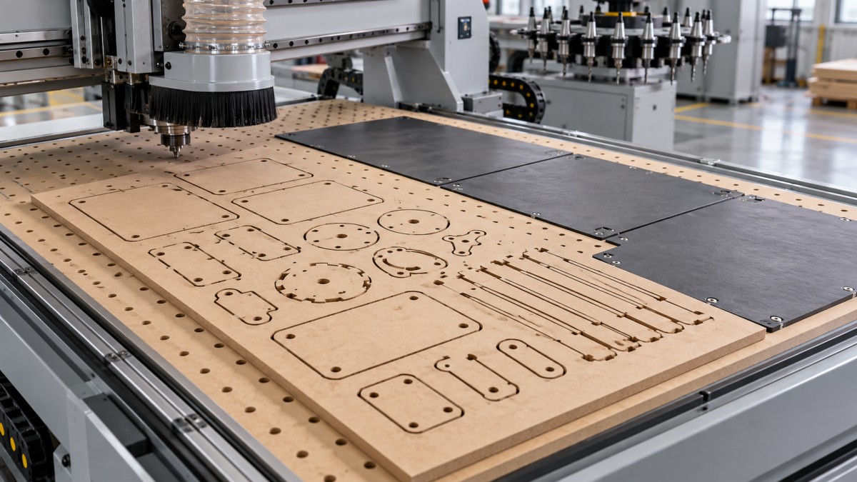
A useful layout drawing shows the active zone, sheet boundary, exposed spoilboard, and the last small parts to be released. This often reveals a mismatch that a pump specification misses: a small component remains connected to the same vacuum supply as a large uncovered area, so much of the available airflow serves leakage rather than retention.
Choose the retention method around the final cut
Direct nesting on a porous spoilboard offers flexible placement and little fixture preparation. It works best when the nesting layout limits exposed area and the smallest components remain stable during finishing. Performance must be demonstrated after neighboring parts have been cut, because an early test contour experiences a different leakage condition from the final contour in the nest.
A gasketed fixture concentrates vacuum beneath a defined footprint. The gasket must form a continuous seal inside the finished perimeter and remain clear of cutters, drilled holes, and through-pockets. Support lands should prevent thin MDF from bending into the vacuum cavity. For narrow parts, gasket width and cutter clearance can leave much less evacuated area than the outer dimensions suggest.
Raw MDF can also leak through its thickness and edges, so a sealed fixture does not automatically produce a sealed workpiece. If that leakage prevents adequate retention, a compatible sealing treatment or a different retention method needs evaluation. Any treatment must remain compatible with later bonding, coating, or finishing requirements.
Onion skinning leaves a thin continuous layer beneath the profile during the main cut. That layer preserves the sheet connection and limits the open airflow path until a separate finishing pass. Its success depends on material thickness variation, spoilboard flatness, and reliable Z referencing. A nominal residual layer offers little protection if local variation allows the cutter to break through early.
Tabs retain physical connections after most of the perimeter is cut. They are useful when vacuum alone cannot resist movement, particularly on narrow or irregular components. Tab position should account for the direction of cutting forces and the stiffness of the remaining connections. Removal and edge cleanup become part of the production process, especially where the finished edge will remain visible.
These methods can be combined. A sheet can use vacuum for overall support, onion skinning during rough profiling, and tabs on the most difficult components. The decision turns on which connection remains dependable through the final tool engagement and how much secondary finishing is acceptable.
Cutting strategy can change the vacuum requirement
Tool geometry affects the direction of force. An upcut spiral encourages chip evacuation while applying an upward component that challenges retention. A downcut geometry presses the upper surface downward but requires suitable chip evacuation, especially in deeper slots. A compression cutter introduces opposing cutting directions; its behavior depends on where the transition between those directions sits relative to the panel thickness and cutting depth.
A compression tool is therefore not an automatic remedy for loose parts. During shallow entry or an unsuitable pass depth, its lower upcut section can dominate engagement. Tool selection must be considered with the actual pass sequence, rather than inferred from the cutter’s label.
Complete internal pockets and drilling while the surrounding sheet still supports the component where practical. Leave external separation until those operations are complete. Position entry moves away from fragile corners, and assess whether the finishing pass applies lateral force where the part has the least resistance to rotation.
Lower feed is not a dependable cure for movement. Excessively low feed for the spindle speed reduces chip thickness and encourages rubbing, heat, and dust. A sharp cutter, suitable chip load, and controlled engagement provide a better basis for evaluation. Tool wear must also enter the decision: a setup that holds only with a fresh cutter has little operating margin.
Make the machine trial reproduce the difficult nest
A meaningful acceptance trial uses the intended MDF, the smallest difficult geometry, and the production cutting sequence. A large rectangle cut from an otherwise intact sheet proves little about small components released late in a dense nest.
Record enough detail to repeat the result: board thickness and condition, spoilboard preparation, open zones, masking, cutter geometry, feed, spindle speed, pass depths, and vacuum measurement locations. On an ATC machine, include the programmed tool changes and Z references. An incorrect tool length can remove an intended onion skin or cut deeply into the spoilboard, changing both retention and leakage.
During the trial, distinguish among failure patterns:
- Movement only at final breakthrough points toward loss of effective retention, an unfavorable finishing force, or an inadequate remaining connection.
- A broad decline in table vacuum as contours open suggests increasing leakage or insufficient flow at the required pressure.
- One part shifts while nearby parts remain stable. Investigate local flatness, dust, geometry, and the pressure path beneath that component.
- Edges deteriorate without measurable part movement. Tool condition, chip evacuation, or cutting parameters deserve attention before changing the vacuum system.
Define acceptance through measurable part position, dimensional results, edge condition, and successful retention across the complete nest. Include representative filter loading and a serviceable cutter with realistic wear. If the smallest component remains secure only while neighboring sheet material is intact, the process still needs a revised separation strategy, a fixture, or a physical connection before production settings are finalized.
Send Your Inquiry
We welcome your cooperation and we will develop with you.