


News & Exhibitions
Latest Factory Updates, Industry Trends & Global Exhibition Information
Nesting CNC or Beam Saw: Which Setup Fits Your Cabinet Factory?
Choose a nesting CNC router when cabinet orders contain varied parts, frequent design changes, and substantial face drilling or routing. A beam saw is a stronger fit when production centers on rectangular panels, repeated dimensions, and enough identical cutting patterns to make stack cutting worthwhile. If both workloads are substantial, a combined setup deserves evaluation—but only after confirming that drilling, edge banding, and material handling can support the added cutting capacity.
The useful comparison is completed cabinet components per shift. Cutting speed alone leaves out sorting, drilling, labeling, and rework. When comparing woodworking solutions for cabinet factories, start with actual order files and trace the work required between full sheets and parts ready for assembly.
Let the order mix determine the cutting method
A factory producing customized kitchens faces a different cutting problem from one making repeated cabinet carcasses. Both process MDF, plywood, and laminated panels, yet their opportunities for batching differ considerably.
Nesting arranges components across a sheet and machines them with a router. Rectangular shelves can share the sheet with shaped panels, service openings, and parts requiring face grooves. Where the machine configuration supports the required operations, cutting and machining use the same setup and coordinate reference. This reduces separate handling, although tool changes and drilling still consume cycle time.
A beam saw divides panels through straight cutting sequences. Its strongest production advantage appears when compatible sheets can be stacked and cut together. That requires matching material, thickness, finish orientation, and cutting pattern. A large daily panel volume does not automatically create useful stacks: many different decors and dimensions can leave the saw processing mostly single sheets.
Batch compatibility also has a scheduling cost. Waiting for enough matching orders to fill a stack can delay urgent cabinets. Evaluate stack cutting against the release quantities the factory actually accepts, rather than assuming every matching sheet will be available simultaneously.
Compare the route to an assembly-ready part
Consider a cabinet side requiring a perimeter cut, shelf-pin holes, a back-panel groove, and connector holes through its edges. A nesting CNC equipped with suitable drilling tools can perform accessible face operations while the sheet remains on the table. Edge holes may still require another machine or an appropriate aggregate. Features on the underside require a second setup unless the production arrangement specifically addresses them.
After beam-saw cutting, the same side panel must pass through drilling and grooving equipment. A dedicated drilling machine can process these operations efficiently, especially with repeated components, but its loading time, queue, and capacity belong in the comparison. A fast saw feeding an overloaded drilling station increases work in progress without increasing cabinet output.
For each representative part family, record the complete route: sheet retrieval, cutting, unloading, identification, secondary machining, and delivery to edge banding. Measure both machine occupancy and direct labor. An automatic cutting cycle may still require continuous attention at unloading, while a longer nesting cycle may leave time for other work if the layout and safe working procedures permit it.
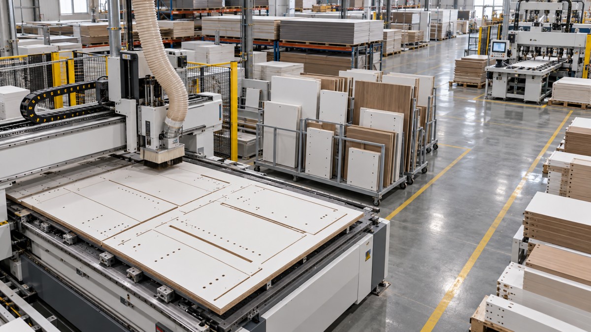
Sorting is particularly easy to underestimate. A nested sheet can contain parts from several cabinets, while a saw stack produces repeated parts that must be separated into orders. Neither arrangement guarantees orderly downstream flow. Labels should remain readable through subsequent operations and identify the part, its orientation, and its next destination.
Material yield changes with tooling and handling
Nesting software can place irregular shapes efficiently, but router diameter creates spacing between components. A saw blade generally removes a narrower strip of material, although the permitted straight cutting sequence constrains the layout. Neither process has an automatic yield advantage across every cabinet order.
Compare optimization results using identical order quantities, sheet sizes, grain restrictions, trim allowances, and remnant rules. Include the actual router diameter or saw kerf. A layout that rotates woodgrain fronts to improve its utilization figure is unusable if the design requires a consistent grain direction.
Offcuts also need a realistic definition. A rectangular remnant becomes useful inventory only when its material, thickness, dimensions, and storage location are recorded and available to later optimization. Otherwise, reported yield can conceal growing piles of untracked material. Small nested scraps and narrow saw strips should be assessed against the factory’s actual reuse practices.
Small parts expose different process limits
On a nesting table, a small component has less area available for vacuum holding. Sheet flatness, spoilboard condition, leakage, material permeability, and the sequence in which surrounding material is removed all affect retention. Movement near the end of a cut can damage dimensions or edge quality even when the machine’s positioning remains accurate.
Leaving a thin material skin for a final pass, retaining tabs, or changing the cutting sequence can improve stability. Each method introduces a tradeoff: another pass takes time, tabs need removal, and final separation must preserve the finished edge. Prove the method with the smallest recurring parts in the production mix.
For beam-saw processing, evaluate narrow-strip handling, minimum clamping dimensions, and support during the final cuts. Stack height must respect the machine’s working limits and demonstrate acceptable quality throughout the stack. A quoted maximum cutting height does not establish that every material and stack arrangement will produce acceptable parts.
Test edge quality under production conditions
Melamine-faced board, veneered panels, and plywood place different demands on tooling. On a nesting router, tool geometry, cutting direction, feed, spindle speed, and cutting depth affect surface chipping and edge finish. A compression cutter requires the correct engagement for its cutting geometry; simply fitting one does not guarantee clean faces.
On a beam saw, blade selection, scoring alignment, pressure application, and panel support influence the result. Inspect the top and bottom faces and, during stack trials, parts from different positions in the stack. A clean top panel can conceal chipping beneath it.
Acceptance should extend through edge banding. A visibly rough routed edge is not automatically unsuitable, and a smooth-looking sawn edge does not prove correct dimensions or squareness. Process trial parts through the intended edge bander, using the planned finishing allowance, and assess the resulting edge and glue line against the cabinet specification.
Dimensional trials should include long panels, narrow parts, and components requiring a second setup. Record finished dimensions and squareness alongside hole-to-edge relationships. For nesting, confirm the finished edge reference after any edge-bander pre-milling; material removed at that stage changes the relationship between previously drilled holes and the final edge.
Where a sliding table saw belongs
A sliding table saw serves a separate role from an automatic beam saw. In a factory built around nesting or beam-saw production, it can handle sample parts, occasional angled cuts, and rework that would interrupt scheduled batches.
For example, the ZD3200 has a 3200 mm maximum cutting length, 1250 mm cutting width between the blade and rip fence, and manual blade tilt from 45° to 90°. Its specified maximum cutting height is 80 mm at 90° and 55 mm at 45°. These dimensions describe its cutting envelope; they do not establish automatic positioning, stack-processing performance, or throughput comparable with a beam saw.
Keeping occasional work on a separate saw can protect the main production schedule. That arrangement still requires space for safe panel movement and a clear method for returning replacement parts to the correct order.
Software and floor space can change the preferred setup
A nesting installation needs more than compatible drawing files. The connection between cabinet design, machining rules, tool definitions, and the machine postprocessor must preserve dimensions, drilling depths, grooves, and part orientation. A successful file import proves little if machining features need repeated manual correction.
For beam-saw production, evaluate cutting optimization together with downstream drilling data. Part identifiers must connect the cut list to the correct machining program. Otherwise, time saved during sizing disappears into program selection, measuring, and sorting.
Test a late design revision as part of the demonstration. Change a cabinet width or connector arrangement and follow the update through optimization, labels, and machining files. The workflow needs a reliable way to prevent superseded parts or programs from remaining in production.
Floor-space comparisons should use working layouts. Include sheet storage, loading access, unloading tables, offcut storage, extraction connections, and queues before secondary machines. Nesting requires adequate vacuum performance and spoilboard maintenance; beam-saw layouts need room for panel movement and the selected feeding arrangement. Confirm electrical, compressed-air, and extraction requirements against the proposed configurations.
Use a production trial to settle the choice
A useful trial contains an ordinary order, a demanding order, and replacement parts released separately. Supply the same source data and acceptance criteria for each proposed setup. Include representative laminated panels or plywood, the smallest recurring components, grain-sensitive parts, and the drilling or routing features that drive secondary work.
Record accepted parts per elapsed hour, direct labor time, material consumed, and work remaining after cutting. Identify why any part failed: movement, chipping, incorrect data, dimensional error, or identification problems require different remedies. Keep setup, tool changes, unloading, and sorting visible in the results.
A combined setup becomes justified when a repeatable rectangular workload can keep the saw productive while varied or machining-intensive parts occupy the nesting CNC. Define the routing rule before adding both machines, and confirm that downstream capacity supports their combined output. The final choice should follow the demonstrated flow of acceptable parts through the factory, with enough capacity at the next operation to turn cutting output into finished cabinets.
Send Your Inquiry
We welcome your cooperation and we will develop with you.