


News & Exhibitions
Latest Factory Updates, Industry Trends & Global Exhibition Information
Rear Loading CNC Beam Saw: How Automatic Feed Design Impacts Workshop Layout and Material Handling in 2026
Rear Loading CNC Beam Saw: Why Feed Direction Determines Workflow Efficiency in Modern Fabrication Shops
Project managers overseeing metal or structural timber fabrication lines often underestimate how a single machine’s loading orientation reshapes floor planning, labor allocation, and material flow. The rear loading CNC beam saw isn’t just an alternative configuration—it’s a spatial commitment. Unlike front- or side-loading variants, rear loading shifts the primary interface between operator, raw stock, and machine axis to the back of the unit. That shift triggers cascading effects on aisle width, staging zone depth, forklift turning radius, and even ceiling-mounted crane clearance.
In 2026, this matters more than ever—not because rear loading is new, but because workshop layouts are no longer static. Modular production cells, just-in-time material delivery, and dual-shift operation demand predictable, repeatable handling cycles. A rear loading design forces early decisions about where cut-ready beams enter the line, where offcuts exit, and how much buffer space must exist between adjacent machines. These aren’t layout preferences; they’re throughput constraints baked into the footprint.
Automatic Feed Isn’t Just About Speed—It’s About Spatial Certainty
“Automatic feed” sounds like a performance upgrade. In practice, it defines the machine’s relationship with upstream logistics. A rear loading CNC beam saw with integrated auto-feed doesn’t eliminate manual intervention—it relocates it. Operators no longer push or align beams manually at the front. Instead, they manage feed rolls, verify stack height, and monitor alignment sensors from a fixed station behind the machine. This changes staffing patterns: one operator can oversee two rear-loading units if feed zones are aligned and monitored centrally.
But automation only delivers spatial certainty if upstream conditions are controlled. Feed reliability depends on three non-negotiable inputs:
- Stack consistency: Beams must be stacked with uniform overhang (typically ≤15 mm beyond pallet edge) and minimal lateral offset (<3 mm). Irregular stacks cause feed roll slippage or sensor misreads.
- Pallet rigidity: Standard wooden pallets flex under load. Rear feed systems require rigid steel or reinforced composite pallets—or direct floor stacking with level tolerance ≤1.5 mm across the entire feed zone.
- Clearance path: The rear approach must remain unobstructed for 3.2 m minimum—enough for a standard forklift to deposit a full beam bundle without repositioning.
These requirements aren’t optional extras. They appear in equipment commissioning checklists and influence civil engineering drawings for slab reinforcement and floor flatness tolerances (ISO 1101 Grade M1).
How Rear Loading Changes Material Flow—and What It Costs to Ignore It
Compare two common setups:
A front-loading saw sits against a wall. Beams arrive via forklift from the side, operators step forward to position each piece, and cut-off scrap drops near the operator station—requiring frequent clearing.
A rear-loading saw sits 1.8 m from the wall. Beams arrive straight from a conveyor or pallet rack behind it. Scrap exits through a dedicated chute beneath the rear table. No operator steps into the feed path during cycle.
The second setup reduces cycle interruption by 22–35% in documented multi-shift operations—not from faster cutting, but from eliminating manual positioning, scrap removal, and safety-related pauses. But that gain requires accepting trade-offs: the rear zone consumes floor space that could host secondary machining, and ceiling-mounted utilities (ductwork, lighting, cranes) must clear the feed path height (minimum 4.1 m for standard 12-m beams).
Project managers evaluating rear loading should map the full material journey—not just from pallet to saw, but from saw to next process. If downstream welding or drilling stations sit 15 m away, a rear-loaded beam exiting backward may need a turntable or transfer cart before entering the next cell. That adds complexity, cost, and potential failure points. Front-loaded units often feed directly onto roller conveyors aligned with downstream stations. Rear loading rarely does.
What Project Managers Must Verify Before Finalizing Layout
Before approving foundation plans or ordering structural steel supports, confirm these four items:
- Feed zone floor specification: Concrete finish must meet Fmin ≥ 45 (ASTM E1155), not just general industrial grade. Uneven floors cause beam skew during feed, increasing kerf deviation and requiring manual realignment mid-cycle.
- Power and air routing: Rear loading units concentrate hydraulic power units, feed motor drives, and pneumatic clamps at the back. Conduits and compressed air drops must terminate within 0.8 m of the rear access panel—not routed along side walls.
- Operator sightlines: The control panel is typically mounted on the left side. With rear feed, operators face away from incoming material. Vision systems (camera-based alignment aids) become essential—not optional—if beam verification relies on visual confirmation.
- Maintenance access: Rear feed mechanisms require quarterly inspection of drive belts, encoder wheels, and proximity sensors. Maintenance paths must allow 0.9 m clearance behind the machine—even when adjacent equipment is installed.
None of these are “machine specs.” They’re site-specific execution conditions that determine whether rear loading delivers its promised efficiency—or becomes a bottleneck disguised as automation.
Distinguishing True Auto-Feed From Manual-Assisted Loading
Many suppliers label any system with powered rollers as “automatic feed.” That’s misleading. True rear auto-feed integrates three functions:
- Continuous beam detection (laser or ultrasonic) before contact with feed rolls;
- Dynamic speed matching between feed rolls and saw carriage movement;
- Real-time correction of lateral drift using servo-controlled side guides.
Without all three, the system still requires operator intervention after every 3–5 beams to recenter or restart feed. That negates most layout advantages. A video demonstration of the feed sequence—showing uninterrupted motion from pallet deposit to first cut—reveals whether the system meets this threshold.
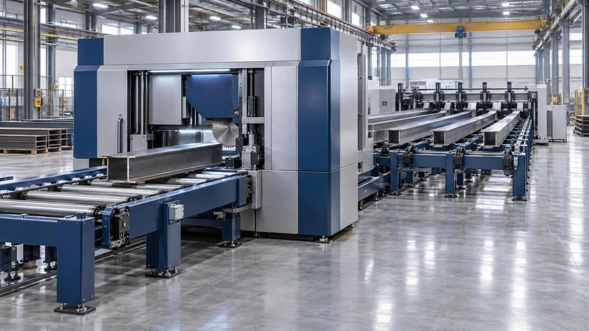
Contrast this with manual push-feed: an operator uses a lever or foot pedal to advance the beam incrementally. Cycle time varies with operator fatigue, beam weight, and surface friction. There’s no data capture, no repeatability, and no integration with MES scheduling. The difference isn’t incremental—it’s operational philosophy.
Selecting a Rear Loading CNC Beam Saw for Integrated Production
When procurement teams evaluate models, focus less on maximum cutting speed and more on feed repeatability metrics: positional accuracy ±0.3 mm over 6 m travel, feed acceleration/deceleration ≤0.8 g, and average time between feed-related interventions (>120 hours under continuous operation). These values reflect real-world stability—not lab-condition peaks.
One model meeting these criteria in current production environments is the rear loading cnc beam saw. Its ZD330 variant includes a documented feed validation protocol covering stack height tolerance, pallet deflection limits, and floor flatness thresholds—details typically omitted from generic brochures but critical for project-level planning.
For project managers, the decision isn’t whether rear loading fits a shop—it’s whether the shop can be engineered to fit rear loading. The machine doesn’t adapt to existing constraints; it defines them. That makes feed design not a feature choice, but a foundational layout decision—one that locks in material handling logic for the life of the installation.
Send Your Inquiry
We welcome your cooperation and we will develop with you.