


News & Exhibitions
Latest Factory Updates, Industry Trends & Global Exhibition Information
Furniture Factory Machinery Layout: Linking Cutting, Edgebanding, and Drilling
A furniture production line works well when panels move between machines with minimal waiting, lifting, and re-sorting. When selecting woodworking machinery for furniture factory operations, plan the connections between cutting, edgebanding, and drilling before fixing machine positions. A fast machine can add little output if its discharge area is blocked or its parts arrive in the wrong sequence.
For panel furniture, cutting → edgebanding → drilling is a useful starting route. The right layout depends on product construction, batch size, edge requirements, and machining strategy. Establish those conditions first, then choose the arrangement, handling equipment, and buffer capacity that keep work moving.
Start with the route each panel actually follows
A floor plan should reflect the parts being produced. A cabinet side, shelf, drawer front, and back panel may follow different routes even when they belong to the same order. Some require four finished edges and several drilling operations; others may bypass edgebanding entirely.
Build a representative part list from the intended product range. Record panel dimensions, material, edge treatment, hole patterns, and production quantity. Include awkward parts such as narrow rails, large doors, and panels with grooves or rebates. These often expose handling problems that standard rectangular parts do not reveal.
Then establish where each operation happens. A nesting CNC router may cut components and machine some face holes in one setup, while horizontal drilling remains downstream. A panel saw route may send more machining work to a separate drilling center. Neither arrangement is universally preferable: the choice depends on nesting efficiency, hole requirements, handling, and the production mix.
Also define whether machining dimensions refer to the cut substrate or the finished panel after edging. Edge thickness, trimming, and machine referencing must agree with the design data. Otherwise, individually accurate machines can still produce components that do not assemble correctly.
Balance capacity using representative production work
Comparing advertised machine speeds does not establish line capacity. Cutting output is often discussed in sheets or parts, edgebanding in feed speed, and drilling in cycles. These measures need to be translated into a common production requirement, such as completed cabinet sets per shift.
For each representative batch, estimate the total work at every stage. Include loading, unloading, tool or material changes, panel turning, scanning, inspection, and normal interruptions. Use available production time after planned breaks and maintenance rather than assuming every scheduled minute produces parts.
A batch of small panels may place a heavy handling demand on the edgebander despite using relatively little board area. Another batch may cut and edge quickly but require extensive drilling. Size capacity around the expected mix and identify which station limits output under each important scenario.
Avoid buying equal nominal capacity at every stage simply to make the proposal look balanced. Some spare capacity can help a station recover after a stoppage. Persistent excess output upstream, however, creates growing queues unless production release is controlled.
Choose the floor arrangement around movement and access
Straight, L-shaped, and U-shaped layouts can all connect the same machines. Their practical differences concern panel travel, operator movement, building constraints, and access for maintenance.
A straight layout suits a building with a clear production direction and enough length for infeed, discharge, and transfer. It makes material flow easy to follow and can accommodate conveyors. Check the complete operating envelope: a machine that fits on the drawing may still lack space for the longest panel leaving it.
An L-shaped layout can work around columns or separate cutting from downstream machining. The corner needs a defined transfer method. Panels must be turned, accumulated, or moved on carts without obstructing either machine.
A U-shaped layout brings parts of the process closer together and may reduce walking when staffing and cycle times permit shared attention. Its suitability depends on keeping incoming material, finished components, pedestrians, and vehicles from competing for the same space. Proximity alone does not make one operator capable of tending several busy machines.
Draw machines to scale with loading positions, open guards, service access, extraction connections, and electrical cabinets. Overlay panel paths and operator paths separately. A short panel route that forces repeated operator crossings may perform worse than a slightly longer, clearer route.
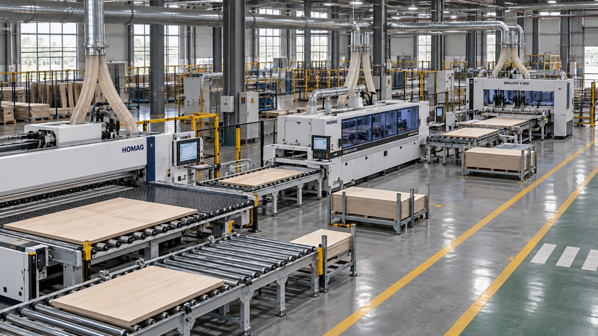
Resolve the cutting-to-edgebanding handoff in detail
The cutting discharge area often determines whether downstream work stays organized. Parts can leave a saw or nesting table in an order that is convenient for cutting but unsuitable for edge processing. They need to be identified and grouped without burying urgent components beneath unrelated work.
Choose a transfer method according to part size, surface sensitivity, output, and batch variation. Carts offer flexibility for mixed orders and changing routes. Roller tables reduce carrying where panels follow a consistent path. Conveyors can support sustained flow, provided their controls, dimensions, and transfer surfaces suit the full panel range.
Specify how small and narrow parts travel. A transfer that handles cabinet sides well may leave narrow strips unsupported. Large panels need sufficient support during turning, while decorative surfaces need clean contact points and protection from sliding damage. Include rejects and reusable offcuts in the plan so they do not occupy the normal discharge area.
At the edgebander, count each required pass. A single-sided machine usually needs the panel to return for additional edges. Manual return, a return conveyor, and a more automated arrangement create different space and labor requirements. Check the complete turning path for the largest panel, including where the operator stands and where waiting parts accumulate.
Batching by edge material can reduce changeovers, but oversized batches delay complete orders. Establish a release rule that balances setup efficiency with assembly priorities. A large pile of edged panels has limited value when each cabinet still lacks one critical component.
Use buffers to absorb interruptions without hiding problems
A buffer gives the next process work during a short interruption and gives the previous process somewhere to discharge. Its capacity should relate to the interruption the line needs to absorb and the rate at which panels arrive.
As a planning calculation, multiply the upstream arrival rate by the intended coverage time. Then check the physical result: the number of panels, their dimensions, stack stability, cart positions, and access space. For edgebanding, distinguish between incoming panels and repeated passes so the calculation does not confuse panel inventory with machine workload.
Separate work awaiting its first edge pass from partially edged parts and panels ready for drilling. Mixing these states makes progress difficult to see and increases the chance of missed operations. Use clearly assigned lanes, carts, or racks, with a visible maximum quantity.
Buffer arrangement also affects retrieval. Flat stacks can be inconvenient when the next panel sits at the bottom. Divided carts or suitable racks may improve access, provided they support the components without damaging edges or surfaces. Keep the area after drilling organized by assembly destination so completed parts can leave production promptly.
Keep panel identity and orientation intact through drilling
Panels that look alike can require different hole patterns. Left and right cabinet sides may have identical dimensions but mirrored machining. Reliable identification therefore needs to survive cutting, handling, edging, and any rework.
A useful panel label links the component to its order, material, edge instructions, orientation, and machining program. Barcode scanning can reduce manual program selection when the software and machines support it. The label position must remain readable and avoid machining areas, trimming, and surfaces where adhesive residue would cause problems.
Define a consistent reference face and reference edge throughout the route. Operators need to know which way to load a part after it has been turned for edging. Where drilling references finished edges, confirm that the program dimensions and machine setup account for those finished dimensions.
If design software, cutting optimization, and machine controls come from different suppliers, demonstrate the actual data exchange before acceptance. Test mirrored parts, different edge thicknesses, and revised orders. A successful file import alone does not prove that orientation, tooling, and machining instructions are correct.
Provide a controlled route for rework. A damaged component may need to return to cutting while the rest of its order continues. Replacement identification should remain linked to the order, with the rejected part removed from normal flow to prevent duplicate or incorrect assembly.
Check utilities and maintenance against the operating layout
Dust extraction, compressed air, electrical supply, and service access can change an otherwise workable floor plan. Plan extraction branches around machine connection requirements and the equipment expected to run simultaneously. Coordinate duct routes with doors, lifting access, and future machine positions.
Review compressed-air demand and quality against equipment requirements, especially where pneumatic clamping and cleaning operate together. Locate electrical isolation and service points where they remain accessible during normal production.
Edgebander glue systems, cutters, drilling units, and extraction points all need maintenance access. Include space for opening covers, removing assemblies, changing tools, and bringing service equipment alongside the machine. Keep material storage and vehicle routes clear of these areas. Reserve expansion space where the likely future constraint sits; unused floor area elsewhere may be difficult to connect later.
Make the layout prove itself before acceptance
Ask equipment suppliers to review the same production brief: representative part files, material range, target output, staffing assumptions, building drawing, and intended expansion. This makes competing proposals easier to compare and reveals differences in what each supplier has included.
Qingdao Zhongding Machinery Co., Ltd. manufactures and exports woodworking machinery and provides technical support and spare parts supply. When discussing a complete woodworking solution, use the production brief to establish equipment suitability, transfer responsibilities, software interfaces, and service requirements.
Acceptance should demonstrate the connected process with representative work. Include large and small parts, multiple edge requirements, mirrored drilling patterns, and an order change. Observe waiting, manual touches, identification errors, and whether completed parts reach assembly in a usable sequence.
Before approving the layout, trace one demanding component through every position it will occupy—from the cutting discharge to its final assembly cart. Identify who moves it, how it turns, where it waits, and how its next operation is selected. Any unanswered handoff is a practical issue to resolve while the layout is still easy to change.
Send Your Inquiry
We welcome your cooperation and we will develop with you.