


News & Exhibitions
Latest Factory Updates, Industry Trends & Global Exhibition Information
Double-Sided Edge Banders: Matching Feed Speed and Panel Width
A double-sided edge bander should be selected by the feed speed it can sustain across the required panel-width range—not by its maximum speed alone. A machine rated for fast feeding may still struggle with narrow, flexible parts, wide panels with insufficient support, or an edge material that requires more time under pressure.
The decisive specification is therefore a combination of width, length, thickness, material, edge construction and required finish at a stated speed. For a façonneuse-plaqueuse double, those conditions also determine whether the upstream and downstream equipment can supply, guide and remove panels without reducing the line’s practical output.
Define panel width in the direction that matters
On a double-sided machine, panel width is the distance between the two edges being processed simultaneously. One side of the machine is generally fixed, while the opposite side is adjusted to accommodate different widths. Panel length is measured in the feed direction. A panel rotated through 90 degrees therefore presents a different width and length to the machine, even though its physical dimensions have not changed.
This distinction matters when evaluating four-sided processing. A rectangular component may pass through one machine or operation with its long dimension across the machine, then be rotated for the remaining edges. The two passes can place very different demands on the width adjustment, support system and allowable spacing between parts. Check both orientations against the operating range rather than using a single nominal panel size.
Ask how the supplier defines minimum and maximum width: between unfinished edges, finished edges, or machine reference surfaces. Also establish whether the range applies at the full specified panel thickness and feed speed, and with all required processing units installed. A catalogue range does not necessarily establish that every combination within it can be processed at the same quality and speed.
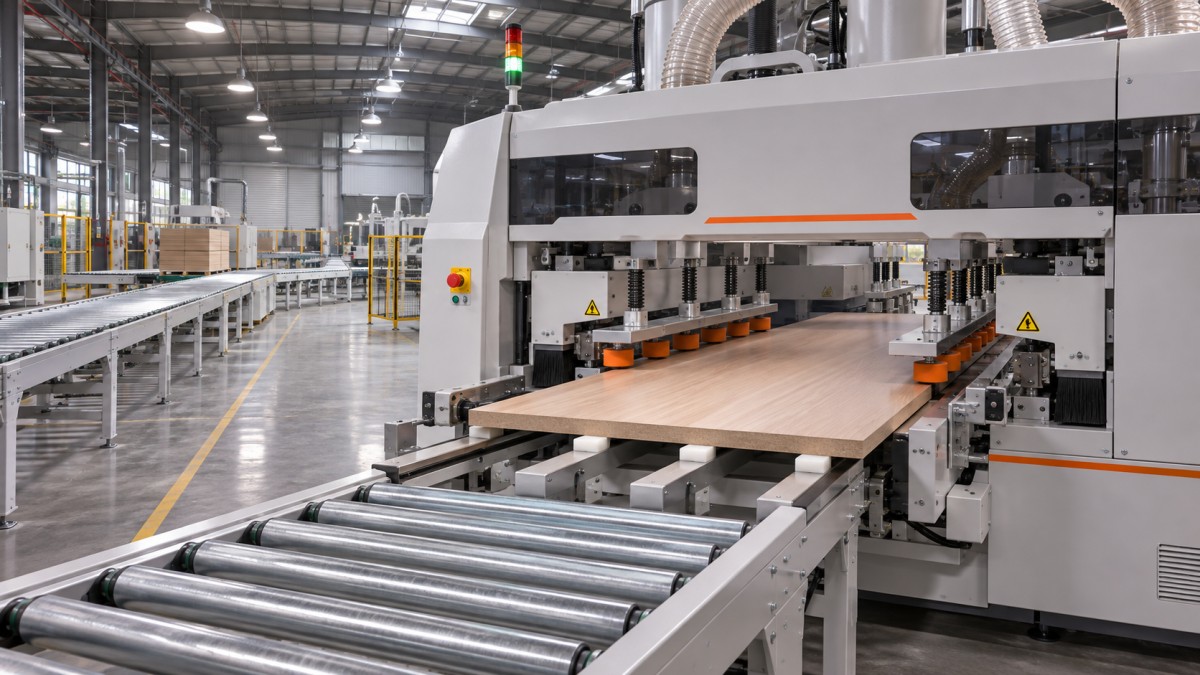
Width affects stability, but not through a simple speed formula
There is no universal equation that converts panel width into a safe feed speed. Width changes how a workpiece is supported and constrained; the resulting speed limit depends on the machine layout and the panel itself.
Narrow panels deserve attention at the minimum-width end of the range. The two processing sides are close together, leaving less room for feed and pressure components. Short or narrow workpieces can also be harder to keep square if they are not positively controlled as they enter and leave each station. Confirm that the specified minimum width applies to the actual length and thickness combination, not just to a long, rigid test panel.
Wide panels present a different problem. The machine must maintain the correct separation between processing sides while supporting the workpiece across a greater span. A thin or flexible panel can sag or vibrate between contact points. If the adjustable side, feed tracks or additional supports do not hold the panel consistently, the two edges may be processed at different heights or the panel may move relative to the tooling.
Width also changes the effect of dimensional variation. The two sides must accommodate the incoming blank without excessive side pressure, while providing the reference and control needed for accurate processing. If upstream cutting produces variable widths or out-of-square blanks, determine whether the machine is intended to size the panel as well as apply edging, and how much material the sizing units can remove under the proposed conditions.
Separate conveyor speed from finished output
Feed speed is normally expressed in metres per minute. Finished throughput also depends on the panel length in the feed direction and the gap required between panels. For a continuous, evenly spaced stream:
Theoretical panels per minute = feed speed ÷ (panel length + gap)
Use the same length unit throughout. At 30 m/min, with panels 1.2 m long in the feed direction and a 0.3 m gap, the theoretical rate is 20 panels per minute. This is an illustrative calculation, not a machine performance claim. It excludes interruptions, rejects, changes of width and any slower equipment elsewhere in the line.
The gap cannot be chosen solely to improve the calculation. End-trimming units, automatic loading, panel detection and downstream handling may each require separation. Some operations may also impose a minimum part length at a given speed. Request the supplier’s permitted length and gap conditions for the complete station configuration.
For a mixed production schedule, calculate output by panel family rather than applying the fastest rate to all parts. A useful comparison includes running time, width-change time, adhesive or edge-material changes, planned stops and expected rework. If four edges require two passes, account for both passes and the rotation or return arrangement; a one-pass panel rate is not automatically a finished-part rate.
Find the station that sets the usable speed
A feed system may be capable of moving a panel faster than the processing units can complete their work. The limiting station changes with the required finish and material combination.
At the infeed, pre-milling or sizing units must remove the specified stock without unacceptable chipping, vibration or dimensional variation. Cutter geometry, spindle speed, number of cutting edges and removal depth all matter. Raising feed speed changes the distance travelled per cutter revolution; it does not necessarily preserve the same surface quality. Verify the proposed speed using the actual board construction and the maximum stock allowance expected from upstream cutting.
At the application point, the adhesive system must deliver a consistent quantity and wet the relevant surfaces. Pressure rollers need sufficient contact under the selected edge and panel conditions. Higher speed reduces the time a given point on the edge spends under each pressure element, so pressure arrangement, adhesive behaviour and available open time must be considered together. A stronger bond should not be assumed merely because the machine has more rollers; roller geometry, pressure settings and material compatibility also matter.
Trimming, scraping and buffing units can establish another limit. A thick edge, a delicate decorative surface or a profile with a small acceptable tolerance may require different tooling or a lower speed than a simple square-edge finish. End-trimming units must operate within the available panel spacing as well as at the selected feed rate. Compare the speed rating of each required unit with the overall machine rating, and ask whether simultaneous operation changes any limit.
Dust extraction and chip removal belong in the same assessment. Processing defects can be caused by debris trapped at the glue line or by chips interfering with tracking, not only by the application unit itself. The extraction system must be specified for the installed stations and connected in a way that does not restrict their operation.
Match the support arrangement to the actual panel mix
Build a panel schedule that includes minimum, maximum and representative widths, but do not stop there. Include length in the feed direction, thickness, core construction, surface finish, edge material and the proportion of each part family in production. Record the required dimensional and finish tolerances as measurable acceptance criteria.
Pay particular attention to combinations that may be valid individually but difficult together: the widest panel at the thinnest thickness, the narrowest panel at the shortest length, and the heaviest panel at the highest proposed speed. These combinations can expose limitations that a list of separate minimum and maximum values does not show.
Examine how the panel is registered and held throughout the machine. Relevant details include the position and length of feed tracks, pressure beams or rollers, entry guides, support between the two sides, and the method of adjusting the movable side. Determine which surfaces establish the reference and whether the panel remains controlled while transferring between successive stations.
For wide formats, check support beyond the machine as well as inside it. An unsupported panel entering at speed can arrive skewed or deflected before the processing units have a chance to control it. At the exit, the handling equipment must prevent the finished panel from dropping, rubbing its fresh edges or colliding with the following workpiece.
Distinguish edge banding from other machining requirements
A production route can involve both panel edge processing and machining of solid-wood joints, but those are different equipment-selection problems. A CNC Mortising machine , for example, is intended for operations such as mortises, slots and grooves. Its processing-length and spindle specifications should not be used to infer an edge bander’s panel-width range, adhesive performance or feed capacity.
Use a conditional acceptance test, not a single demonstration panel
A meaningful supplier demonstration or factory acceptance test should reproduce the operating window that matters. Agree the test conditions before comparing machines, especially if the quotations state different maximum speeds or use different definitions of panel size.
- Workpieces: identify panel dimensions, thickness, core and surface materials, incoming squareness and any permitted variation.
- Edge construction: specify edging material, thickness, adhesive system and the intended joint appearance.
- Machine configuration: list all stations in use, tooling, extraction connections, support devices and automatic handling equipment.
- Operating conditions: state feed speed, panel orientation, spacing, stock removal and any changes made between part sizes.
- Acceptance measurements: agree how to assess finished width, squareness, edge position, trim quality, chipping, glue-line appearance and bonding performance.
Test the narrow and wide limits, the critical short and thin combinations, and a representative production part. A sustained run is more informative than a single good panel because it exposes repeatability, heating behaviour, adhesive supply consistency and handling interruptions. The run duration and sample quantity should be agreed according to the production requirement rather than treated as universal values.
Measure both edges and compare results along the panel length. A defect appearing only near the leading or trailing end can point to a control, support or end-trimming issue that an average width measurement would miss. Inspect the panel after any specified conditioning period if the adhesive or acceptance procedure requires it; an immediate visual check alone does not establish long-term bond performance.
If the required quality is achieved only after reducing speed, record that speed as the demonstrated operating point for that particular material and setup. It may still meet the production target, but it should not be represented as proof that the same finish is available at the machine’s maximum rated feed.
Specify an operating window that can be verified
The most useful purchase specification links each critical panel family to a width and length range, feed speed, station configuration, edge material and acceptance criteria. It should also state the allowable changeover method and the interfaces required for loading, unloading and extraction. This makes it possible to compare proposals on the same basis and identify where an offered machine needs additional support or a different processing configuration.
A higher maximum speed is valuable only if the panel can be controlled, the stations can complete their work and the rest of the line can maintain the required spacing. Where those conditions differ across the product mix, the appropriate machine is the one whose verified operating window covers the demanding combinations—not necessarily the one with the largest speed figure.
Send Your Inquiry
We welcome your cooperation and we will develop with you.