


An automatic tool changer CNC router usually appears to lose its Z offset because of incorrect tool compensation, inconsistent tool seating, reference errors, or mechanical movement.
When cutting becomes too deep or leaves material uncut after a tool change, the resulting errors can scrap panels, damage tooling, and interrupt production.
For after-sales maintenance technicians, the priority is identifying which reference changed: tool length, work zero, machine position, or the physical relationship between components.
This guide explains how to separate those faults, verify measurements safely, and restore consistent cutting depths without hiding the original problem behind repeated offset adjustments.
First, identify what actually changed in the Z reference chain
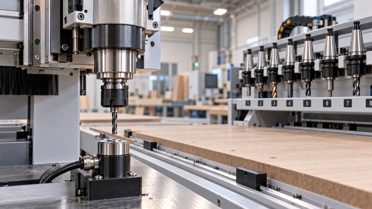
The displayed Z coordinate does not independently prove where the cutting edge sits. Its meaning depends on the active coordinate system and tool compensation state.
Machine position comes from the axis reference established by homing or the machine’s position feedback system. Its reliability depends on the specific control architecture.
Work zero defines the job reference, commonly the panel surface or spoilboard. Tool-length compensation accounts for the distance between the spindle reference and cutting tip.
A tool setter supplies a measurement used within this system. Its trigger position, calibration, and measurement routine must remain consistent for reliable tool offsets.
Finally, mechanical components must maintain their relationship. A slipping cutter, contaminated holder interface, or moving Z assembly can change cutting depth without changing stored offsets.
Before editing anything, record the active work coordinate, selected tool, applied length register, machine Z position, and the event immediately preceding the depth error.
Use the symptom pattern below to choose the next check. These patterns narrow the investigation; none should be treated as a conclusive diagnosis.
Make the machine safe and capture evidence before resetting offsets
Stop production when the depth error threatens the spoilboard, fixtures, or tool changer. Preserve alarms and offset records before power cycling or clearing diagnostics.
Follow the manufacturer’s isolation procedure before reaching into the spindle, tool magazine, or Z-axis mechanism. Support gravity-loaded assemblies wherever the service procedure requires it.
For powered diagnostic moves, clear the enclosure, keep personnel outside the motion area, and use the manufacturer’s approved setup mode with appropriate speed limits.
Do not bypass spindle-clamp confirmation, tool-presence sensing, or guarding to reproduce a fault. An unsuccessful clamp can turn a depth problem into tool ejection.
Save the program, relevant tool table, work offsets, and accessible macro settings. Record controller and software versions so later comparisons use the same configuration.
Ask whether the fault began after a tool replacement, collision, software change, spoilboard resurfacing, or maintenance visit. Each event suggests a different diagnostic starting point.
Record the error’s direction and approximate magnitude against a known reference. A repeatable discrepancy is easier to trace than an operator’s description of inconsistent cutting.
If one tool is wrong, check tool identity and seating first
Confirm that the physical cutter, magazine pocket, displayed tool number, and active length register match. These relationships are configurable and may differ between machines.
A correct tool call does not always guarantee correct compensation. Some controls use separate length-register commands; others manage the relationship through machine-specific macros.
Inspect the failing tool’s entry for incorrect units, unexpected signs, duplicate values, or manual changes. Compare it with a previously verified measurement where available.
For example, replacing a cutter with one projecting farther from the holder changes its effective length. Reusing the old measurement can cause an immediate depth error.
Inspect the collet, nut, cutter shank, and holder interface for dust, resin, damage, or incorrect assembly. Clean components using the spindle and holder manufacturer’s instructions.
On taper systems, contamination can prevent consistent seating. On other interfaces, inspect the specified locating surfaces and clamping features rather than assuming identical maintenance requirements.
Check cutter projection before and after a controlled test. A changed projection indicates movement within the holder, even when the stored tool-length value remains unchanged.
Use specified tightening methods and torque values. Excessive tightening, worn collets, unsuitable shank engagement, or contamination can all undermine retention and measurement repeatability during operation.
If seating remains inconsistent, inspect clamping status and the specified air supply conditions. Drawbar force or internal spindle work may require qualified spindle service personnel.
If repeated measurements disagree, isolate the tool setter and probing routine
A tool setter cannot provide dependable offsets if its trigger point changes. Dust, resin, sticking mechanisms, damaged cables, or unstable mounting can affect repeatability.
With the spindle stopped, inspect and clean the accessible sensing surface according to the maintenance instructions. Confirm that the assembly is secure before measuring again.
Repeat the approved measurement routine several times with one verified tool. Record individual readings and their spread, then compare them with the manufacturer’s repeatability specification.
Do not invent a universal acceptance limit. The permitted variation depends on the machine, setter design, application tolerance, and uncertainty of the verification method.
If readings vary, observe the input state through controller diagnostics using the approved procedure. Intermittent transitions can suggest switching, wiring, contamination, or electrical interference problems.
A stable trigger does not prove correct calibration. A setter moved during maintenance can produce repeatable measurements that are consistently wrong for every tool.
Check the calibration reference, measurement approach direction, feed settings, and any stored setter height. Restore values only from verified records or an approved calibration procedure.
Also confirm whether the routine writes absolute tool lengths, relative corrections, or work offsets. Misunderstanding its purpose can make a normal measurement appear to erase Z.
If every tool shifts, inspect work zero, homing, and compensation commands
When multiple verified tools show approximately the same depth error, investigate shared references before changing individual tool lengths. Start with the active work coordinate system.
Confirm that the program uses the intended work offset and datum convention. A panel-top datum and spoilboard datum require different setup assumptions throughout the workflow.
Check for unintended local shifts, temporary coordinate changes, or probing routines that update work zero. Their availability and cancellation behavior depend on the controller.
Review the program around tool changes and restarts. On controls using G43, G49, and H registers, verify their sequence against the machine’s programming documentation.
For instance, a restart may select the correct tool while skipping the block that activates its length compensation. The resulting error can resemble lost memory.
Some woodworking controllers handle compensation internally, so generic G-code advice may be inappropriate. Compare the postprocessor output with a proven program for that exact machine.
If the fault follows power loss or emergency recovery, verify the required referencing procedure. Do not assume the displayed machine coordinates remained physically valid.
Compare the recovered position with an approved fixed reference. If homing is inconsistent, investigate the reference sensor, mounting, approach conditions, and relevant drive diagnostics.
If depth changes during cutting, test mechanical position and workholding
An offset table cannot correct an axis that physically loses position. Investigate this branch when cutting depth changes under load or after rapid movement.
Depending on the drive system, possible causes include excessive resistance, unsuitable acceleration settings, coupling movement, feedback faults, or mechanical looseness in the Z assembly.
Check alarm history and following-error information where available. Closed-loop feedback can detect many position discrepancies, but detection depends on the feedback location and control configuration.
A motor encoder may not detect movement downstream of a slipping mechanical connection. Compare commanded movement with an independent indicator or approved reference measurement.
Inspect accessible fasteners, couplings, lubrication condition, and counterbalance components under the prescribed service procedure. Avoid changing tuning parameters before identifying mechanical resistance or looseness.
If Z drops when the drive is disabled, inspect the brake or counterbalance system according to the manufacturer’s instructions. Secure the assembly before servicing.
Also check the panel and spoilboard. Vacuum loss, panel bowing, accumulated debris, or spoilboard movement can change the cutting surface while machine coordinates remain consistent.
Separate static and load-related behavior through controlled checks. A tool that measures correctly while stationary may still slip or deflect once cutting forces increase.
Verify the repair through the sequence that originally failed
After correcting the identified cause, restore calibration and offsets using the approved procedure. Avoid compensating for an unresolved fault by adding an arbitrary Z correction.
First verify repeatability with a known tool and reference. Then perform repeated tool exchanges, including the affected magazine pocket, while checking seating and measurement consistency.
Run a controlled test on sacrificial material using a proven program. Include the tool-change sequence that triggered the complaint and measure the resulting feature depth.
If the original fault followed restart or power recovery, validate that workflow separately under the manufacturer’s procedure. A successful uninterrupted cycle leaves that condition untested.
Document the measured error before repair, the identified cause, corrective work, and verification results. Include relevant settings and component details to support future service calls.
For machine-specific assistance, provide Qingdao Zhongding Machinery Co., Ltd. with the machine model, serial number, controller details, alarm records, and the smallest program reproducing the fault.
An automatic tool changer CNC router maintains reliable depth when tool measurement, coordinate references, seating, and axis position remain consistent throughout the complete operating cycle.
The practical rule is simple: determine which reference changed, repair that cause, and verify the original failure sequence before releasing the machine back into production.