


News & Exhibitions
Latest Factory Updates, Industry Trends & Global Exhibition Information
What Configuration Does an MDF Sander Need for 480V, 60Hz Power?
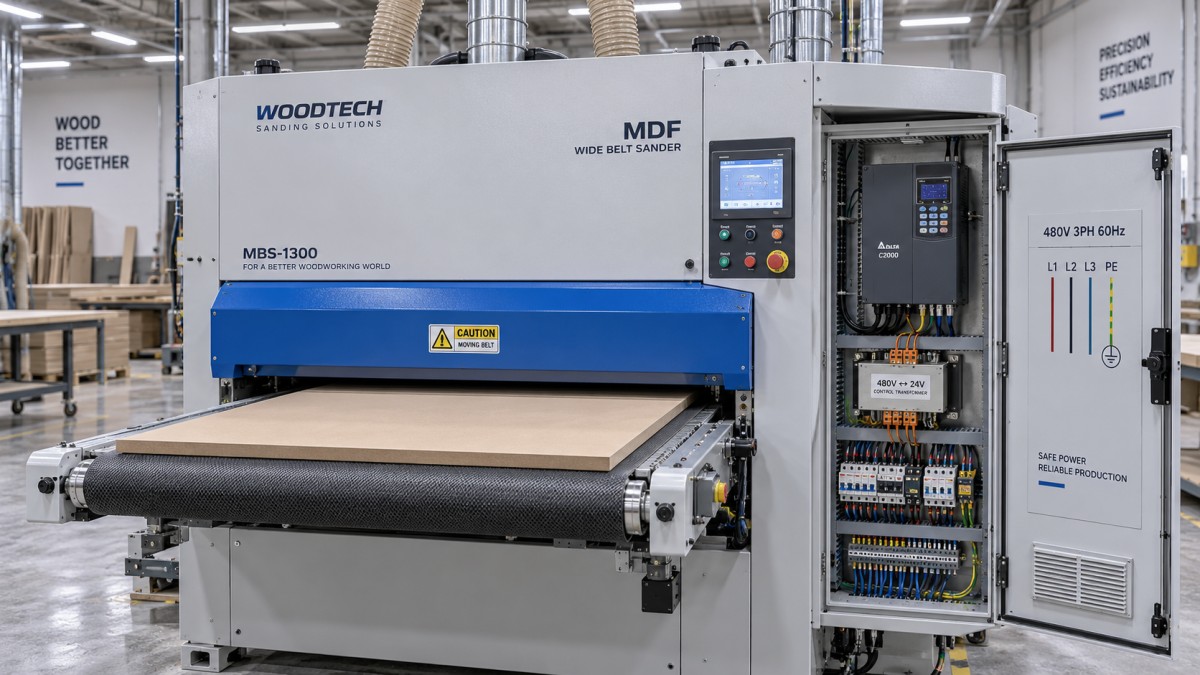
An MDF sander connected to 480V, 60Hz power needs a compatible three-phase electrical system throughout the machine: motors, drives, control power, switching components, and protective devices. A suitable motor nameplate alone does not establish that the complete sander is ready to connect.
The right MDF sander 480V 60Hz configuration also depends on the available supply, sanding-belt speed, feed system, and installation requirements. Before ordering or converting a machine, establish its incoming-power specification and require an electrical drawing that shows how every circuit receives the correct voltage and frequency.
Start with the incoming supply and the complete machine rating
Specify the required supply as 480V, three-phase, 60Hz, then establish whether the machine needs a neutral conductor in addition to the phase conductors and protective earth. Many industrial machines derive their control voltage internally and do not require a neutral, but this must match the actual circuit design.
Protective earth and neutral serve different functions. A grounding conductor must never substitute for a missing neutral. Likewise, the presence of a neutral in the building does not mean that the machine needs one.
The supply arrangement matters as well. Grounded wye, delta, and other systems can affect the suitability of variable-frequency drives, surge-protection devices, and filters. Give the supplier the supply arrangement along with the nominal voltage. “480V available” leaves out information needed to select some electrical components.
Use the following checks to turn a general voltage request into a defined configuration.
Read every motor nameplate, including the smaller motors
An MDF wide-belt sander may have separate motors for sanding heads, conveyor feed, thickness adjustment, brushes, and other functions. Each needs a compatible supply or a correctly selected drive. Checking only the largest sanding motor can leave an incompatible auxiliary motor hidden inside an otherwise suitable machine.
A 460V, 60Hz motor can be appropriate on a nominal 480V supply. In common North American practice, the motor utilization rating allows for voltage drop between the supply and the motor terminals. The decision still depends on the motor’s permitted operating range and the voltage it actually receives. A 460V marking is not automatically evidence of a mismatch.
A motor marked 380V or 400V requires a different assessment. Some motors have multiple approved winding connections; others cannot accommodate 480V through reconnection. Star and delta connections are specific winding arrangements, not universal voltage-conversion options. Follow the motor’s connection diagram and the machine’s engineered design.
Record rated current as well as power. Two motors with the same stated kilowatt output can require different drive settings and overload protection. Replacement motors also need suitable mounting, shaft dimensions, enclosure, duty, and speed characteristics.
Resolve the frequency difference before selecting a conversion method
A sander originally designed for 50Hz power needs more than a voltage adjustment. For a directly connected induction motor, changing supply frequency changes its operating speed. That can increase sanding-belt speed, alter conveyor feed, and change the relationship between material removal and panel travel.
Higher sanding speed is not automatically useful. Contact drums, bearings, pulleys, and abrasive belts have operating limits. Changes can also affect heat generation, surface finish, and the load on the sanding head. The acceptable speed must come from the machine design and the abrasive specification.
A transformer changes voltage; it does not change frequency. Supplying a 400V, 50Hz machine through a transformer connected to a 480V, 60Hz source still leaves the machine operating from 60Hz power. That arrangement is suitable only when the remaining equipment and mechanical speeds are designed to accept it.
There are several practical approaches:
- Order a factory-configured 480V, 60Hz machine. This allows motors, controls, protection, and operating speeds to be selected together.
- Convert an existing machine through an engineered modification. This may involve motor replacement or reconnection, control-power changes, drive selection, and revised documentation.
- Use a transformer where voltage is the remaining mismatch. This can suit equipment already compatible with 60Hz operation, provided the transformer is sized for the connected load and starting conditions.
Compare the complete conversion scope before choosing. An inexpensive transformer can become a poor purchase if the machine also needs new motors, control components, and mechanical changes.
Configure drives around the motor and the sanding process
If the sander uses variable-frequency drives, their input ratings must accept the available 480V supply. Output-current capacity must suit the connected motors and their operating loads. Selecting a drive solely by the same horsepower label as the motor can overlook overload duty, enclosure temperature, and other application conditions.
Commissioning parameters should reflect the actual motor nameplate: voltage, current, frequency, and speed. Acceleration, deceleration, overload protection, and maximum output frequency also need to match the machine.
A drive can control motor frequency independently of the incoming frequency, which may help preserve an intended operating speed. However, compatibility still depends on motor voltage, insulation, cooling, and the drive’s output characteristics. Installing a drive does not automatically make any motor suitable for any supply.
The sanding head and conveyor need separate attention. Sanding-belt speed influences the cutting action, while feed speed determines how long the panel remains under the head. Preserving one while changing the other can produce a different finish or excessive material removal.
Deceleration deserves particular care because sanding assemblies retain rotational energy. An aggressive stop setting may cause drive faults or require braking provisions. Emergency-stop behavior must be designed around the machine’s hazards and safety circuits; an ordinary drive stop command alone does not establish an adequate safety function.
Make control power and protection part of the specification
The PLC, sensors, contactor coils, valves, and display may use voltages different from the main supply. A machine can have compatible sanding motors and still suffer immediate control-component damage if its control transformer is connected incorrectly.
For a transformer with multiple primary taps, the selected connection must match the incoming supply. Electronic power supplies must also have an appropriate input range. Review coil and fan ratings individually, especially where components run directly from line power.
The electrical design should identify how the machine receives power, how faults are cleared, and how motors are protected from overload. These functions are related but distinct. A branch-circuit protective device does not necessarily provide the motor overload protection the application needs.
Do not size the feeder by dividing total motor power by supply voltage. Three-phase current also depends on efficiency, power factor, simultaneous operation, and starting behavior. Use the machine’s electrical ratings and installation information to establish feeder conductors, disconnect rating, and protective-device selection under the applicable installation rules.
The machine’s short-circuit current rating also needs to suit the available fault current at its connection point. This concerns the panel assembly and its components, not simply the number printed on the incoming breaker.
MDF dust affects electrical reliability too. Cabinet sealing, cooling, filter maintenance, and component placement should suit the installation environment. Dust accumulation can restrict cooling and contaminate equipment. Coordinate extraction and housekeeping with the machine installation, including any required dust-system interlocks.
Check the installation before running a panel
Qualified electrical personnel should complete connection and electrical commissioning using the machine’s drawings. The useful checks extend beyond whether the main motor starts.
- Inspect the delivered configuration. Match the machine plate, motor plates, drive ratings, transformer connections, and drawings to the ordered specification.
- Measure the incoming supply. Check phase-to-phase voltage and frequency, then investigate significant voltage imbalance. Repeat relevant measurements during starting and operation to identify excessive voltage drop.
- Check grounding and control power. Establish protective-bonding continuity and correct control voltages before normal operation.
- Verify rotation and tracking using the prescribed procedure. Check sanding heads, feed direction, and associated equipment. Phase changes at the input will not necessarily reverse a motor controlled by a drive.
- Test operating and safety functions. Include emergency stops, access interlocks, feed controls, extraction permissives where fitted, and restart behavior after power loss.
- Run representative MDF panels. Monitor motor current, drive faults, belt tracking, surface quality, and operating stability at the intended production settings.
An unloaded run cannot establish performance under sanding load. Begin with controlled settings and increase loading within the machine’s rated capability. Record the successful parameters so later adjustments and maintenance have a reliable reference.
If a breaker trips during starting, identify whether the cause is starting current, voltage drop, incorrect settings, a fault, or mechanical resistance. Increasing breaker size without checking the circuit can leave conductors or equipment inadequately protected. Similarly, repeated drive trips should be diagnosed before changing protection thresholds.
Put the required configuration in the purchase specification
A useful order description goes beyond “480V version.” State the supply, required operating speeds, feed range, control-voltage arrangement, installation environment, and documentation requirements. Ask for the machine’s rated input current, starting method, connection details, and electrical drawings before preparing the installation.
For a quotation from Qingdao Zhongding Machinery Co., Ltd., include the site power details and intended MDF sanding process in the same request. Its woodworking-machinery and technical-support offering is relevant to coordinating the machine specification, spare parts, and later service. The electrical configuration should still be documented for the particular machine being supplied.
The practical acceptance point is a machine whose complete electrical system matches the site supply and whose sanding and feed speeds remain within its intended design. Establish those details before shipment, then use the agreed drawings and commissioning records to bring the sander into production.
Send Your Inquiry
We welcome your cooperation and we will develop with you.