


News & Exhibitions
Latest Factory Updates, Industry Trends & Global Exhibition Information
Double-Sided Planer Selection: Feed Speed, Stock Size, and Finish Quality
Select a double-sided planer by the feed speed it can sustain on your actual stock while meeting thickness and surface requirements. Maximum working width, motor power, and advertised feed speed are useful screening figures, but none establishes production capacity on its own. A machine that feeds quickly yet leaves tear-out or inconsistent thickness can increase sanding, rework, and material loss.
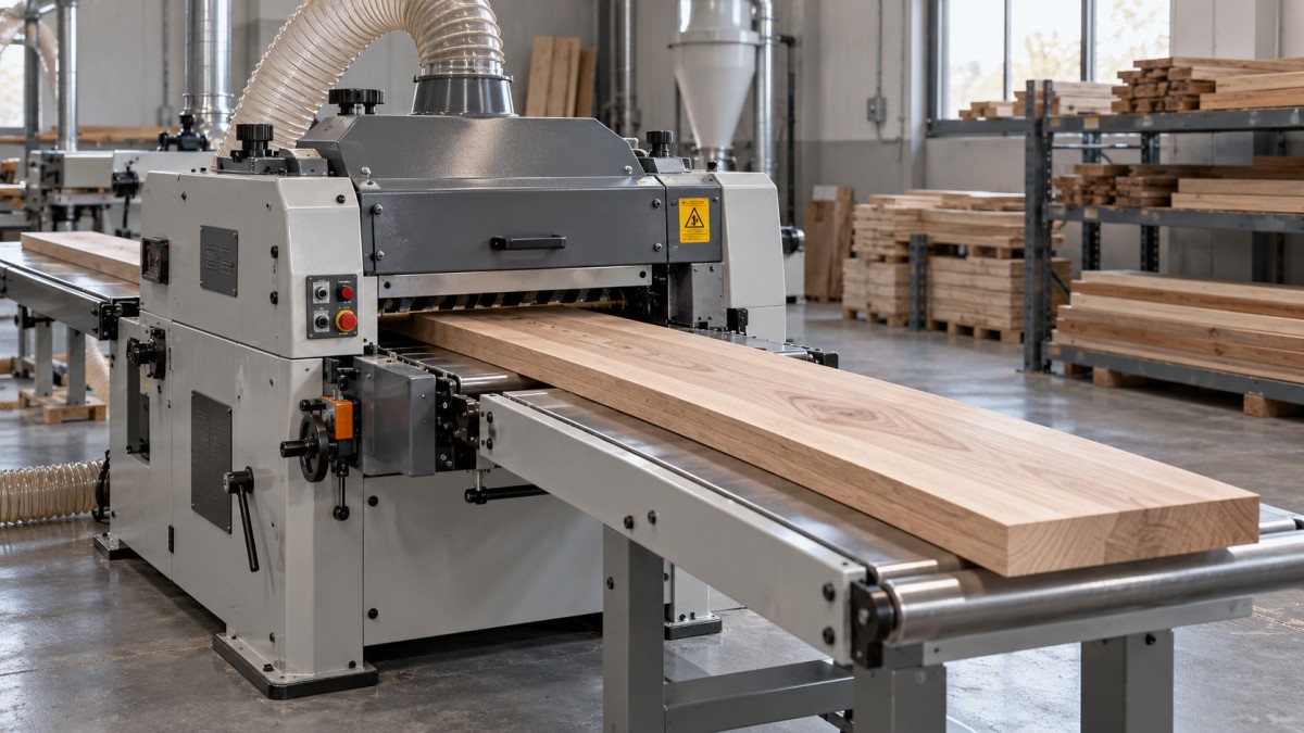
A double-sided planer, also searched for as a raboteuse 2 faces, machines the upper and lower faces in one passage. Its suitability depends on how the cutting system, stock support, and feed mechanism work together. Start with the incoming material and required output, then assess which configuration can bridge the gap consistently.
Define the stock range before comparing machines
Prepare a stock specification that includes species, moisture condition, incoming width and thickness, finished dimensions, and board length. Record normal production sizes separately from occasional extremes. Buying around one unusually wide component can add cost without improving everyday output; buying around average dimensions can leave a recurring part outside the machine’s capacity.
Nominal dimensions are only part of the assessment. Rough-sawn boards can have thickness variation, cup, bow, twist, knots, and uneven ends. These conditions affect feeding, material removal, and the amount of usable timber remaining after machining.
Minimum workpiece length deserves as much attention as maximum width. Short components must remain controlled as they pass between feed elements and cutterheads. Ask for the permitted minimum length for the proposed machine and operating arrangement. Long boards present a different problem: inadequate infeed or outfeed support can disturb their position and affect the cut.
Check whether the machine can establish the reference face you need
Machining both faces does not automatically make a distorted board flat. A thicknessing arrangement may press a bowed board against its support during cutting; when the pressure releases, some curvature can return. The resulting board may have relatively consistent thickness while still failing a flatness requirement.
Double-sided planer designs differ in their ability to establish a lower reference face. Cutterhead arrangement, table geometry, and the way the board is guided all matter. Evaluate the proposed machine’s surfacing capability instead of assuming every two-face configuration handles rough, distorted stock equally well.
If the process needs flat furniture components, specify flatness and thickness consistency separately. Where incoming distortion exceeds the machine’s practical capability, upstream surfacing, stock sorting, or a different machining sequence may be necessary. More cutting depth alone will not resolve inadequate referencing.
Choose feed speed around acceptable output
Feed speed affects both production rate and the spacing of cutting marks. With cutterhead speed and effective cutting-edge engagement unchanged, increasing feed speed increases the distance the board travels between successive cuts. This generally produces a coarser surface pattern. Reducing feed speed can improve that pattern, but it cannot compensate for dull tooling, vibration, poor support, or difficult grain.
For a conventional straight-knife cutterhead, the basic relationship is:
Feed per knife = feed speed ÷ (cutterhead rotational speed × effective number of knives).
Use consistent units when making this calculation. It helps explain surface-mark spacing, but it does not predict finish quality by itself. Knife projection, cutting geometry, wood structure, and machine condition also influence the result. For segmented cutterheads, total insert count should not be treated as an equivalent straight-knife count; the engagement pattern differs.
A useful feed range must cover the work you actually run. Repetitive stock with modest removal may support faster feeding. Wide hardwood boards, heavier cuts, or reversing grain may require a lower speed to keep cutting load and defects under control. Variable feed is valuable when these conditions change between batches.
Compare machines at the same acceptable result. If one needs slower feeding but eliminates a sanding pass, it may deliver better overall productivity. Conversely, a visually finer planed surface has little value if the next operation removes it anyway.
Also distinguish conveyor speed from completed output. Board gaps, loading delays, stock sorting, tool changes, and downstream congestion reduce production below the theoretical feed rate. Capacity planning should use accepted parts per operating period, with realistic handling and maintenance allowances.
Evaluate cutting capacity as a combined load
Working width, cutting depth, and feed speed are often listed separately, although they draw on the same cutting and feeding resources. A machine may accommodate a wide board and offer a substantial depth adjustment without being able to sustain both at its highest feed speed.
As a practical guide, material removal rate increases with cutting width, depth of cut, and feed speed. Wood species, moisture condition, and tool sharpness then affect the power needed to make that cut. Compare proposed machines using a defined operating condition, such as your widest regularly processed hardwood at the intended removal and finish.
Examine upper and lower cutting duties individually. Stock may need different removal from each face, especially when the lower cut establishes a reference and the upper cut brings the board to final thickness. Separate cutterhead power ratings and permitted cuts are more informative than a single total connected-power figure.
Heavy removal can also create problems beyond motor load. It increases chip volume and may aggravate tear-out or feeding difficulty. When rough stock varies substantially, staged machining can be more controllable than demanding a finished result in one aggressive pass. The machine specification should reflect the intended process.
Match the cutterhead to the material and maintenance plan
Straight-knife cutterheads remain a practical choice for consistent stock and workshops equipped to sharpen and set knives accurately. Their performance depends on sharp edges, correct projection, and balanced cutting engagement. Poor setting can leave one knife doing a disproportionate share of the work, affecting finish and tool life.
Segmented carbide-insert heads can simplify edge maintenance because individual inserts can be indexed or replaced. Designs using a shearing cutting action may improve results on some difficult-grain materials. However, labels such as “spiral” and “helical” do not describe every supplier’s geometry consistently. Examine insert orientation, cutting angle, and the specified tooling.
Do not select an insert head solely on an expectation of smoother surfaces. Results depend on the wood, insert condition, cutting depth, and feed setting. Insert seating cleanliness and correct tightening also matter; maintenance errors can create visible lines or uneven cutting.
Compare tooling over a realistic service cycle. Include sharpening or replacement cost, changeover time, local availability, and the skills required to restore the machine to production. A suitable cutterhead should fit both the cutting task and the workshop’s maintenance capability.
Feed control and support determine thickness consistency
A rigid frame helps maintain alignment, but machine weight alone does not establish accuracy. Table condition, cutterhead alignment, bearing condition, feed pressure, and stock support all contribute to the result. Ask how adjustments are made and how wear-related components are serviced.
Feed pressure requires balance. Insufficient grip can allow slipping or uneven travel, especially under heavier cutting loads. Excessive pressure can mark the surface or compress flexible stock during machining. On distorted boards, pressure may temporarily flatten the material without permanently correcting its shape.
The roller arrangement must suit the surface being handled. Gripping elements that work well on rough timber may leave marks if they contact a finished face. Check the position and type of feed rollers, along with the practical adjustment range for your stock.
Snipe—an unwanted deeper cut near a board end—deserves explicit attention during evaluation. It can arise when support or pressure changes as the workpiece enters or leaves the cutting area. Inspect both ends of trial boards, because a good central surface can conceal a trim allowance that reduces yield.
Dust extraction belongs in the capacity assessment too. Inadequate chip removal can contribute to recutting, surface defects, and interruptions. Match the installation to the machine’s specified extraction requirements, including airflow and pressure needs, rather than choosing ductwork by connection diameter alone.
Use a production trial to compare shortlisted machines
A useful demonstration reproduces the conditions most likely to expose a mismatch. Include representative stock and a demanding sample within the intended operating range. An easy, narrow board with light removal tells little about performance on wide components or difficult grain.
Agree on the acceptance criteria before machining:
- Dimensions: Measure thickness at multiple positions along the board and across its width.
- Geometry: Assess flatness separately from thickness consistency, with the board free from feed pressure.
- Surface condition: Inspect both faces for tear-out, cutter marks, roller impressions, and chip damage.
- End quality: Record snipe and any trimming needed to obtain an acceptable component.
- Process performance: Record feed setting, removal from each face, handling interruptions, and downstream sanding needs.
Use measurement methods and acceptance limits that match the finished product. A concealed structural component and a visible furniture part may justify different surface requirements. Evaluate boards promptly, while accounting for moisture-related movement if later measurements form part of acceptance.
Keep the trial conditions comparable between suppliers. Differences in stock preparation, tooling condition, or removal allowance can make one machine appear more capable without demonstrating an equivalent task. Record these conditions alongside the results so the purchasing decision remains traceable.
Turn the results into a purchase specification
The final specification should connect a defined stock range to an accepted result at an agreed operating condition. Include working dimensions, minimum piece length, removal requirements, tooling, feed adjustment, dimensional criteria, surface expectations, extraction needs, and handling arrangements. State which incoming defects require sorting or preparation before planing.
Support arrangements also affect long-term usability. For an overseas purchase, discuss spare-parts identification, tooling supply, setup documentation, and access to technical assistance. Qingdao Zhongding Machinery Co., Ltd. manufactures and exports woodworking machinery and provides technical support, spare parts, and after-sales service. These are relevant procurement considerations alongside the proposed machine configuration and trial results.
Send shortlisted suppliers the same stock description, finished-part requirements, and acceptance procedure. Ask each to identify the configuration and operating conditions needed to meet them. That creates a useful basis for choosing a double-sided planer: repeatable, acceptable output from your material, with a maintenance and support arrangement your production team can sustain.
Send Your Inquiry
We welcome your cooperation and we will develop with you.