


News & Exhibitions
Latest Factory Updates, Industry Trends & Global Exhibition Information
Choosing solid wood door machinery for stile-and-rail joints
Choosing solid wood door machinery for stile-and-rail joints
In stile-and-rail door production, joint accuracy affects assembly efficiency, bond quality, and long-term stability. Choosing solid wood working machinery for doors therefore requires more than comparing spindle power or feed speed: technical evaluators must assess profile matching, tenon tolerances, workpiece referencing, and tear-out control across different timber species. This guide examines the machining capabilities, tooling compatibility, and production requirements that matter when selecting equipment for consistent stile-and-rail joints, helping you identify solutions that support repeatable quality while limiting rework and setup time.
The useful starting point is not a machine catalogue. It is a joint drawing, a representative selection of timber, and a clear description of the doors the workshop actually needs to produce.
Define the joint before choosing the machine
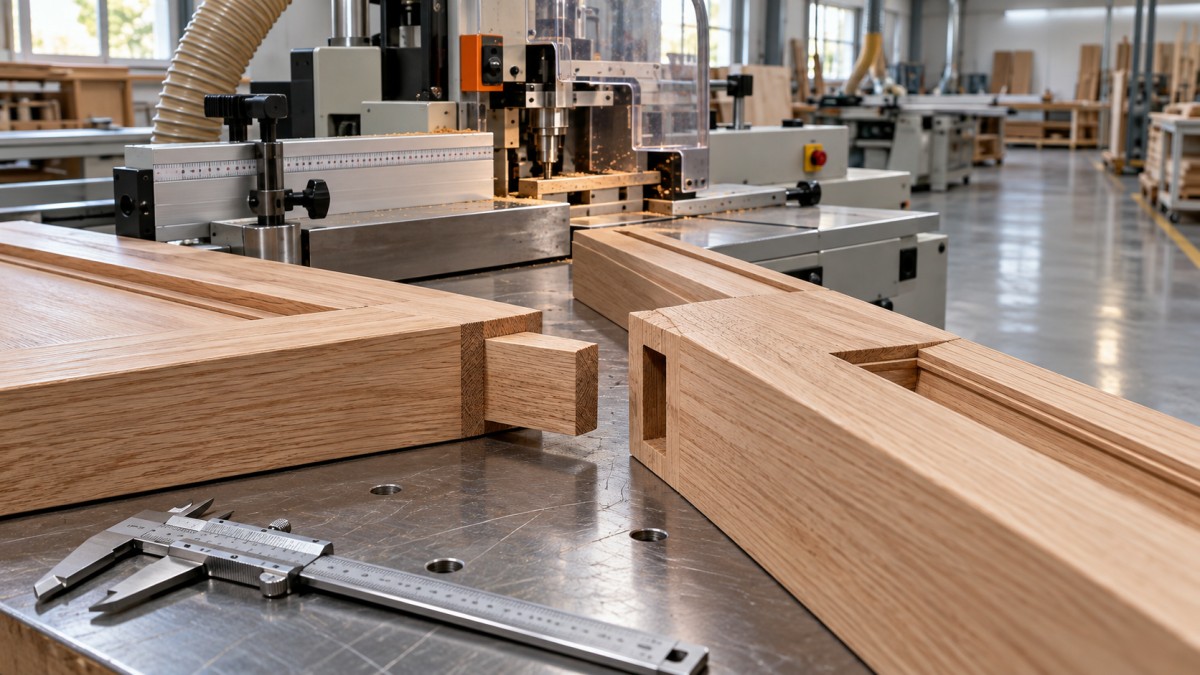
“Stile-and-rail joint” can describe different constructions. A cope-and-stick joint combines a profiled rail end with a matching stile profile. Depending on the tooling and design, it may incorporate a short integral tongue. A traditional mortise-and-tenon joint uses a tenon entering a mortise, sometimes with a haunch to accommodate the panel groove. Loose-tenon construction requires corresponding mortises in both members.
These are not interchangeable machining tasks. A machine that produces a clean decorative cope does not automatically provide the tenon length or mortise capability required by a particular door design. Joint strength must be assessed for the intended construction and service conditions; appearance alone is not a reliable acceptance criterion.
Before requesting quotations, establish the member thicknesses, rail widths, profile sections, panel-groove position, tenon geometry, and finished shoulder-to-shoulder dimensions. Include the narrowest rail and widest bottom rail, not just a convenient middle-size sample. These extremes often expose clamping and tool-clearance limitations.
Choose a production route that matches the order mix
A spindle moulder with suitable tooling, guarding, and a secure end-coping carriage can suit workshops producing varied profiles in modest batches. It offers flexibility, but repeatability depends heavily on stops, tooling setup, feed arrangements, and operator practice. Safe workholding for short rail ends needs particular attention.
Dedicated tenoning and mortising machines separate joint-making from longitudinal profiling. This can be a practical arrangement when the design requires substantial integral tenons or when profiling and joinery have different capacity requirements. The trade-off is additional handling and the need to preserve references between machines.
Double-end tenoners are worth evaluating for repeat batches where machining both rail ends in one setup reduces handling and controls finished length. Their suitability still depends on minimum part length, rail width, available machining heads, and the actual joint geometry. The machine category alone does not establish those capabilities.
CNC machining centres may be attractive for mixed designs, mortises, and other door-component operations. However, programmed flexibility should not be confused with economical output. Fixture changes, tool access, machining time, and loading can outweigh the benefit for a workshop running the same joint all day.
Compare complete routes rather than isolated machines. Include stock preparation, profiling, joint machining, inspection, and assembly. A fast tenoner provides little benefit if inconsistent incoming thickness forces operators to sort and rework components.
Joint consistency starts with reliable references
Many apparent tooling problems begin with workpiece referencing. If one operation references the finished face while another references a variable-thickness opposite face, the resulting profile step may look like cutter mismatch. Regrinding the tooling will not solve that cause.
Ask the supplier to show exactly how each component sits against the table, fence, end stop, and clamps. Establish a consistent reference face and edge throughout the route. Where components must be flipped, confirm how the fixture or program compensates rather than relying on operator interpretation.
Clamping must resist cutting forces without distorting the stock. Narrow rails need sufficient support close to the cut, while wide rails need stable support against lifting or rotation. A machine demonstration using only thick, straight, generously sized blanks leaves these questions unanswered.
Incoming material deserves equal scrutiny. Moisture condition, bow, twist, and thickness variation affect machining and later assembly. Define the acceptable blank condition before attributing every rejected joint to machine accuracy. Equipment cannot remove the consequences of uncontrolled material movement after machining.
Evaluate the tooling system, not just spindle power
Matched rail-end and stile-profile cutters should be evaluated as a system. Confirm spindle interfaces, rotation direction, permitted tool diameter, usable spindle length, and the speed range required by the proposed cutters. Compatibility must cover the complete assembly, including spacers, retention components, guarding, and extraction arrangements.
Motor power matters, particularly with large profiles or heavier cuts, but it cannot compensate for unsuitable cutting geometry or poor support. Ask how the recommended tooling handles the intended species, grain direction, profile depth, and finish requirement. The answer should involve more than increasing feed speed.
End-grain breakout deserves a separate trial. Depending on the machine and tooling, control may involve a sacrificial backing piece, a scoring operation, opposed machining units, or an appropriate cutting sequence. Any arrangement must follow the machine and tooling supplier’s safety instructions; improvised feed-direction changes are not an acceptable substitute.
Also establish what happens after sharpening or insert replacement. Can matching profiles be maintained? Are setting dimensions documented? Are replacements available from a practical supply source? A tooling package that performs well initially but becomes difficult to restore is a production risk.
Turn “good fit” into a measurable acceptance test
There is no single joint clearance suitable for every species, adhesive, and construction. An excessively tight tenon can complicate assembly and adhesive distribution; excessive clearance can compromise joint performance. Set acceptance limits around the approved joint design and adhesive requirements rather than adopting an unsupported universal tolerance.
A supplier trial should use production-representative material and include more than one successful sample. The following checks reveal different failure modes:
- Dimensional repeatability: inspect tenon thickness, mortise dimensions, shoulder position, and finished rail length across consecutive components.
- Interchangeability: assemble randomly selected rails and stiles rather than keeping individually matched pairs.
- Surface and profile quality: examine shoulder gaps, face alignment, crushed fibres, breakout, and tool marks at the visible profile junction.
- Reset performance: change to another job, then return to the original setup and check whether the approved dimensions are recovered.
- Assembly behaviour: check insertion force, squareness, and whether normal clamping closes the joint without disguising machining errors.
Dry fitting is necessary, but it is not proof of bond strength or long-term door stability. Where performance requirements demand it, include bonded samples and appropriate testing in the qualification plan. Keep machining acceptance separate from structural validation.
Measure output through the working day
Published feed speeds describe only part of production. For a realistic comparison, record loading, positioning, machining, unloading, inspection, and changeover time. Count accepted components, not simply completed machine cycles.
Small-batch production often rewards reliable presets and straightforward changeovers more than maximum cutting speed. Longer runs may justify automated feeding or linked operations, provided upstream preparation and downstream assembly can keep pace. Automation added to an unstable process can produce rejected parts faster.
Inspection access also affects usable output. Operators should be able to check critical dimensions without lengthy disassembly or unsafe access. Clearly defined setting gauges, reference samples, and inspection points can make a simpler machine easier to control than a more elaborate system with an unclear adjustment process.
Assess extraction, guarding, electrical supply, compressed air, and installation space alongside capacity. Confirm the applicable destination-market requirements and the documentation supplied with the actual machine configuration. Do not assume that an optional guarding or extraction arrangement is included in the base quotation.
Treat support and delivery scope as technical criteria
Long-term accuracy depends partly on maintenance access and support. Ask which components require routine inspection, how spindle and fence settings are restored after service, and which wear parts should be held locally. Clarify responsibility for tooling setup, operator training, commissioning, and troubleshooting before delivery.
Qingdao Zhongding Machinery Co., Ltd. is a woodworking machinery manufacturer and exporter with more than 20 years of industry experience. Its stated provision of complete woodworking solutions, technical support, spare parts, and after-sales service is relevant to this evaluation. Those capabilities should be translated into a project-specific scope: which operations are covered, what training is included, and how replacement parts and remote assistance will be arranged.
When shortlisting solid wood working machinery for doors, send each supplier the same joint drawings, material specifications, production mix, and acceptance requirements. Request trials on the difficult parts as well as the routine ones. The stronger choice is the machine-and-tooling combination that repeatedly produces interchangeable joints, returns predictably after changeovers, and can be maintained under your workshop’s actual conditions.
Send Your Inquiry
We welcome your cooperation and we will develop with you.