


News & Exhibitions
Latest Factory Updates, Industry Trends & Global Exhibition Information
Which solid wood machines can produce curved staircase handrails?
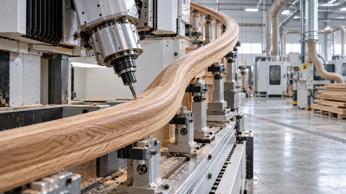
CNC machining centres, copy routers, and dedicated handrail profiling machines can produce curved wooden staircase handrails, but they handle different geometries. A three-axis CNC router can machine many flat curved components with suitable setups; a five-axis machining centre is often better suited to rising, twisting rails and complex transitions. Copy routers and spindle moulders can also be practical when templates, workholding, and cutter access match the design.
The selection problem usually appears when a handrail drawing moves beyond a simple curve: the rail rises around a stairwell, changes pitch at a landing, or carries an asymmetric profile that must retain its orientation. Selecting equipment only by spindle power or working length can leave surfaces inaccessible or joints misaligned. First establish whether the machine must create the curved blank, profile an already curved blank, or do both.
Define the curve before comparing machines
“Curved handrail” can describe several substantially different machining tasks. A rail curved in one plane is not equivalent to a helical rail, even when their plan views look similar. The following distinctions determine the required axes, fixtures, and process route.
- Planar curve: The rail centreline lies in one plane. Flat curved landing rails and some curved fittings fall into this category. Their outline is often accessible with conventional routing methods.
- Rising or helical curve: The rail turns horizontally while gaining height. Tool orientation and clearance become more demanding, especially around the underside and inside radius.
- Transition fitting: A wreath, turnout, or pitch-changing connection joins rail sections with different directions or slopes. These short components may be harder to machine than a long, regular curve.
- Changing cross-section orientation: A non-circular profile must follow a defined orientation along the rail. This requires more control than simply sweeping a round section along a centreline.
Supply a three-dimensional model where possible, including the finished profile, joint faces, connection details, and intended orientation. A plan drawing alone may conceal changes in pitch or twist. Distinguish the finished rail dimensions from the larger blank needed for clamping and machining allowance.
Which machine fits each handrail task?
Three-axis CNC: useful when access is straightforward
A three-axis machine can cut a curved outline from a thick blank, rough the top surface, and machine accessible profile details. Turning the component over in a registered fixture may provide access to the remaining surfaces. For planar rails and simple fittings, this can be a workable route without five-axis investment.
The weakness is repositioning. Each setup introduces another opportunity for datum error, particularly on a long, flexible component. Ask how the supplier will locate the second setup and blend the machined surfaces. A fourth-axis attachment may expand capability, but a standard rotary unit designed for straight workpieces does not automatically accommodate a sweeping curved rail.
Five-axis CNC: stronger capability for spatial geometry
Five-axis machining allows the tool to approach surfaces from changing directions. It can reduce repositioning and improve access to rising curves, twisted profiles, and compound fittings. However, the axis count alone does not prove suitability.
Some designs can be produced with indexed, or 3+2, machining, where the head is positioned before a three-axis cut. Others benefit from simultaneous five-axis toolpaths. Require the proposed process to demonstrate which method is needed. Check collisions involving the spindle housing, toolholder, clamps, and workpiece—not just the cutter tip.
Long-tool reach is another constraint. A machine may reach the surface geometrically but require excessive tool projection, reducing rigidity and surface quality. Evaluate the actual tool assembly and cutting strategy inside the proposed fixture.
Copying and dedicated profiling equipment
Copy routers are attractive when a workshop repeatedly produces the same fitting or curve family. Their accuracy depends on the master, follower arrangement, cutter geometry, and workholding. A machine that copies an outline in one plane should not be assumed capable of reproducing a three-dimensional wreath.
Dedicated handrail profilers can be efficient when the curved blank already exists and needs a consistent cross-section. Their capabilities vary substantially. Some arrangements suit planar curves; others accommodate selected spatial forms. Request confirmation using the tightest radius and most difficult transition in the intended product range.
A spindle moulder remains an option for suitable curved blanks, but not as an unrestricted substitute for CNC. Guided fixtures, pressure devices, guarding, and support must be engineered for the operation. Irregular short fittings or severe changes in grain direction may make another process preferable.
Machining a curve is not the same as bending timber
When comparing solid wood working machinery for stairs, separate blank manufacture from final shaping. A router removes material; it does not bend a straight rail into a stable curve. The blank-making route affects material yield, grain direction, machining allowance, and the equipment required upstream.
Machining from thick stock can suit short fittings and some broad curves. However, cutting across a blank can create short-grain regions, particularly around tight changes in direction. Geometrical accuracy does not establish structural suitability. Grain continuity and joint design must be assessed against the handrail’s intended loading.
Bent lamination builds a curved blank from thin solid-wood strips bonded around a form. This requires strip preparation, suitable adhesive, controlled clamping, and a stable forming fixture. It is distinct from machining a single solid timber blank, although the resulting component is commonly processed with woodworking machinery. Confirm whether laminated construction is acceptable in the specification.
Steam bending is another possible route for suitable timber and geometry. Success depends on species, stock quality, section, moisture condition, tooling, and drying control. Springback and dimensional change must be allowed for before final profiling. Neither bending route eliminates the need to establish machining datums after the blank has stabilised.
The fixture often determines whether the machine can deliver
A long curved rail can deflect under cutting forces even when the machine itself is rigid. Supporting only the ends may allow vibration, chatter, or local dimensional error. Supports should follow the workpiece closely enough to control movement without blocking tool access.
Vacuum holding is not automatically sufficient. Narrow sections, porous timber, irregular undersides, and machining through a sealed area can reduce holding force. Mechanical clamps, dedicated nests, sacrificial locating features, or combined systems may be needed. Their position must be checked throughout the toolpath.
Discuss these details before accepting a machine proposal:
- Datums: Identify the reference surfaces or locating features used from roughing through final joint machining.
- Release sequence: Establish when temporary tabs, extensions, or clamping allowances are removed and how the nearly finished rail remains supported.
- Working envelope: Check the complete curved blank, fixtures, tool assembly, and head movement rather than comparing rail length with table length.
- Sectional manufacture: If the rail exceeds practical machine capacity, define joint locations and how adjacent sections will be aligned.
Joint faces deserve particular attention. Two individually accurate rail sections can still produce a visible step if their profiles are referenced differently. Machining joint features from consistent model datums reduces dependence on manual correction during assembly.
Tooling, timber, and finishing change the production result
Curved rails expose changing grain directions along a single toolpath. A strategy that cuts cleanly on one portion may tear fibres on another. Tool sharpness, cutting direction, engagement, and supported exit conditions all influence the result. Feed and spindle settings should be established for the actual species, cutter, and machine rather than copied from a generic recommendation.
Profile cutters can produce a consistent section efficiently where access allows. Ball-nose or other contouring tools offer flexibility for spatial shapes but can leave scallops requiring sanding. Toolpath spacing, cutter diameter, and local curvature determine that finishing burden. A visually acceptable machined surface is not necessarily ready for coating.
Assess moisture condition before machining and stability after unclamping. Timber movement can change joint alignment or profile dimensions after an apparently successful machine cycle. Laminated blanks also require appropriate adhesive cure and conditioning before finishing cuts.
Dust extraction must reach the cutting zone through changing head positions. For enclosed CNC equipment, confirm that extraction and guarding remain effective with the proposed fixtures. For manually guided shaping, verify that the curved work can be fed and supported without unsafe exposure to the cutter.
Use a representative acceptance trial, not a simple demonstration piece
A straight rail sample or a broad planar curve cannot validate a machine intended for helical staircase work. Provide a test component that includes the smallest intended radius, the most demanding pitch transition, the actual profile, and representative timber. Include a mating section if joint continuity matters.
- Confirm the complete route. Record blank preparation, fixture loading, roughing, repositioning, finishing, and joint machining.
- Verify geometry after release. Measure the centreline, cross-section orientation, critical radii, and joint faces against agreed drawing tolerances after unclamping.
- Inspect difficult surfaces. Examine the inside radius, underside, grain reversals, and setup boundaries for tear-out, chatter, or blending marks.
- Record remaining labour. Include sanding, fitting, template preparation, and manual correction when comparing production effort.
- Demonstrate repeatability. Repeated loading and machining should confirm that the fixture locates consistently, not merely that one carefully adjusted part is acceptable.
For varied three-dimensional rails and transition fittings, prioritise a capable five-axis process with proven CAM and fixtures. For mostly planar curves, evaluate three-axis machining before adding complexity. Repeated curved blanks with stable profiles may favour dedicated profiling or copying equipment. The decisive evidence is a complete, repeatable process for the hardest required component—not a machine label or an unloaded cutting demonstration.
Send Your Inquiry
We welcome your cooperation and we will develop with you.