


News & Exhibitions
Latest Factory Updates, Industry Trends & Global Exhibition Information
Sizing a Woodworking Dust Collector to Meet Shop Airflow and Safety Needs
Start With the Air Each Machine Actually Requires
A dust collector is correctly sized when it captures dust at each machine source, carries that material through the ductwork without settling, filters the exhausted air appropriately, and continues to do so when the shop is operating as planned. A collector selected only by its catalog airflow rating can look adequate on paper and still leave dust on floors, haze in the work area, poor machine pickup, or a duct system that plugs at elbows and branches.
For quality and safety managers, the first decision is whether the collector must support one machine at a time, a defined group of machines, or a production area that may run several processes simultaneously. The answer determines nearly every later calculation. Adding the airflow labels from every machine in a building is usually excessive; assuming that only one machine will ever run can be equally unsafe if work practices change or operators bypass an interlock.
The working airflow target should be based on the equipment connected during the highest credible operating condition. That condition may be a panel saw and edge sander running together, several CNC stations under scheduled production, or a central system serving a line with automatic sequencing. It should reflect the actual operating plan, not an informal assumption that users will remember to close blast gates.
Build the Airflow Calculation From Machine Demand
Each woodworking machine needs enough air movement at its pickup hood to pull chips and fine dust away from the cutting zone. The required volume depends on the machine design, hood opening, chip load, and material being processed. A wide-belt sander, for example, produces a large volume of fine dust and often requires substantial extraction capacity. A jointer or thickness planer may generate heavier chips that demand reliable transport velocity as well as adequate volume. CNC routing can create a different challenge: fine dust may escape around the tool if the dust shoe is poorly designed, even when the central collector is large.
Machine manuals and hood specifications should be the starting point whenever available. Record the recommended airflow, port diameter, number of ports, and whether the stated requirement applies to one port or all ports operating together. A machine with two extraction ports is frequently under-served when both are joined into an undersized branch or one port is capped without confirming that the hood still captures effectively.
For a system with simultaneous use, calculate the design airflow by adding the required airflow for each machine expected to operate at the same time. Then review the operating sequence. If a machining center, saw, and sanding station can all run during normal production, their demand belongs in the design case. If equipment is truly interlocked so that only one of several stations can operate, the collector may be sized around that controlled combination rather than the sum of every connected machine.
Blast gates can reduce unnecessary airflow only when they are consistently closed, clearly assigned, and compatible with the way work is performed. Manual gates are often less dependable in busy shops because they rely on operator behavior. Automated gates tied to machine controls provide a more defensible basis for diversity assumptions, provided their opening sequence, fail position, and maintenance responsibilities are defined.
- List every machine, its dust ports, and its documented airflow requirement.
- Identify which machines can operate together during normal and peak production.
- Include secondary sources such as downdraft tables, floor sweep connections, bin vents, or sanding booths if they are connected to the same system.
- Separate future expansion from current demand, then decide whether capacity will be reserved now or added later through a planned system extension.
A common error is to treat a large main duct as evidence that enough airflow is available. Duct diameter affects resistance and conveying velocity, but it does not create air volume. The fan, filter condition, duct losses, and open branches determine the delivered airflow at the machine.
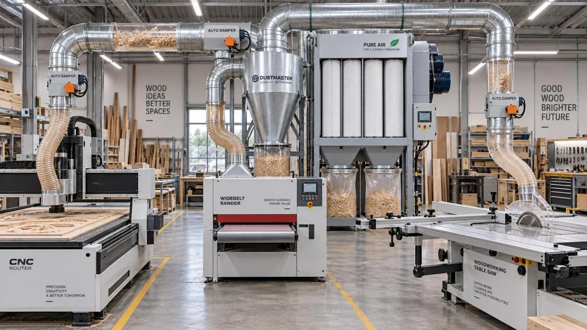
Airflow Alone Does Not Size the Collector
After the required volume is established, the system must be evaluated for static pressure. Static pressure is the resistance the fan must overcome to move the required air through hoods, branches, fittings, main duct, separator, filter media, and discharge path. Fan performance changes as resistance rises. A collector may be advertised with a high free-air airflow figure, yet deliver far less once connected to a real duct network and a loaded filter.
The design calculation should follow the most demanding airflow path: generally the route from the collector to the machine or group of machines that combines the highest loss with the airflow required at that point. That path can include a restrictive hood, undersized flexible hose, several elbows, a long branch run, a separator, and a filter that gains resistance in service. The path is not always the physically farthest machine. A nearby sanding machine with a restrictive pickup arrangement can impose more resistance than a more distant planer on a straight duct run.
Every component matters. Long runs of corrugated flexible hose, tight-radius elbows, abrupt reducers, poorly designed wyes, and partially closed blast gates can consume a disproportionate share of available fan pressure. Flex hose is useful for vibration isolation and short machine connections, but it should not quietly become the main duct system. Where a long flexible connection is unavoidable, it deserves explicit treatment in the pressure calculation.
Filter condition also belongs in sizing. A clean filter and a filter carrying normal dust loading do not have the same pressure drop. Systems that are acceptable immediately after cleaning can become marginal before the next maintenance interval. If production cannot tolerate declining pickup, the design needs adequate fan pressure at the expected operating filter resistance, together with a cleaning method that keeps the filter within its intended range.
The fan curve is therefore more useful than a single airflow claim. Confirm that the selected fan can supply the calculated air volume at the calculated total static pressure. This verification should use the actual fan configuration, motor rating, impeller arrangement, and intended electrical supply. Changing ductwork, adding a fine filter, or installing a cyclone separator after the original selection can move the operating point enough to reduce collection performance materially.
Keep Transport Velocity Separate From Hood Capture
Two airflow questions are often blended together: will the hood capture dust, and will the duct carry it to the collector? Both must be satisfied, but they are not the same calculation.
At the machine, airflow must be sufficient to pull dust into the hood before it disperses into the shop. Hood geometry, enclosure quality, and the location of the source all affect this result. An open sanding operation may require a different control approach from a well-enclosed machine port. Increasing fan size will not fully correct a hood that leaves the dust generation zone exposed.
Inside the duct, the air must move quickly enough to keep wood chips and dust entrained. If velocity falls too low, material can settle in horizontal runs, accumulate in elbows, and create recurring blockages. If duct diameter is increased without revisiting airflow, velocity drops. If too many branches remain open, the air available to each active machine can also fall below its required capture level.
This is why “bigger duct is always better” is incomplete advice. A larger main can lower resistance and accommodate higher total airflow, but it must be matched to the system’s operating volume. Likewise, a very small duct may produce high velocity while starving the machine hood of the air volume it needs. The appropriate diameter comes from both the intended airflow and the need to maintain reliable material transport.
Filtration Is a Workplace Exposure and Process-Control Decision
Collector capacity should not be evaluated only by how much visible dust reaches the bin. Fine wood dust may remain airborne long after chips have been captured, and a system that leaks around seals, uses damaged media, or exhausts inadequately filtered air back into the work area can undermine the purpose of extraction.
The filtration choice depends on whether air is returned indoors or discharged outdoors, the wood species and coatings processed, the shop’s housekeeping conditions, and applicable local requirements. Air recirculation usually demands closer attention to filter integrity, media performance, gasket sealing, cleaning effectiveness, and maintenance discipline. A filter’s stated efficiency is not enough by itself; bypass leakage, torn bags or cartridges, poor pulse-cleaning performance, and overloaded media can all affect actual conditions in the shop.
For safety and quality teams, a differential-pressure indicator is often one of the most practical controls. It gives a repeatable signal that filters are loading or cleaning performance has changed. It should be used with a documented response: inspection, cleaning, replacement, or investigation of an unexpected pressure change. A very low reading can also merit attention if it indicates a broken filter, open access door, or another loss of system resistance.
Fine dust control also affects product quality. Deposited dust can interfere with coating preparation, contaminate assembly areas, obscure machine guards, and increase cleanup time. These effects may appear before airborne dust measurements or employee complaints reveal that extraction performance has deteriorated.
Design for Combustible Dust Risk, Not Just Cleanliness
Wood dust can present a combustible-dust hazard when fine particles accumulate, become suspended, and encounter an ignition source under the right conditions. A dust collection system should therefore be reviewed as part of the facility’s broader fire and explosion risk assessment, rather than as a housekeeping accessory.
The required controls vary with the material, process, local code, equipment location, and whether the collector is indoors or outdoors. The assessment may need to address ignition-source control, grounding and bonding, spark detection or suppression where appropriate, explosion protection, isolation between connected equipment, safe discharge arrangements, and emergency response. The applicable legal and technical requirements are jurisdiction-specific, so a design should be checked against the standards and authority requirements governing the installation location.
One misconception is that a collector installed outside the main work area automatically resolves the hazard. Outdoor placement can change the exposure to people and building interiors, but it does not eliminate risks in ductwork, bins, filters, discharge points, or connected machinery. Another misconception is that a clean shop has no dust hazard. Hidden accumulations above ceilings, on structural members, inside ductwork, and around collectors can be more significant than the dust visible near a machine.
A robust inspection program looks beyond the collector’s hopper. It checks duct joints, access doors, flexible connectors, blast gates, filter housings, dust-bin seals, fan vibration, unusual noise, and evidence of material settling in branches. Inspection findings should feed back into the airflow and maintenance plan. Repeated chip buildup, for example, is a system-performance signal, not simply a cleaning problem.
Allow for Expansion Without Oversizing Blindly
Future capacity deserves consideration, especially where a shop expects to add a CNC router, sanding equipment, or another production cell. However, selecting an oversized collector without a duct and operating strategy can create low-velocity conditions when only part of the system is active. The better approach is to identify likely additions, reserve physical space and connection points where useful, and determine whether the fan, duct mains, filter area, and electrical infrastructure can support a defined expansion stage.
Variable-speed fan control can help a central system respond to changing demand, but it must be commissioned around minimum and maximum airflow limits. Reducing fan speed to save energy is beneficial only when active branches still receive enough capture airflow and duct velocities remain suitable for the material being conveyed. The controls should reflect measured system behavior, not merely motor load.
Commissioning should include airflow verification at representative machines, confirmation of blast-gate and interlock operation, inspection for leaks, and a record of baseline static pressure or differential pressure. Those values give safety and quality personnel a reference point for future troubleshooting. Without a baseline, a gradual loss of extraction can remain unnoticed until dust escapes at the machine or production conditions have already degraded.
The most defensible sizing decision connects four items: the machines that will operate together, the airflow each source needs, the pressure losses imposed by the actual duct and filtration system, and the safety controls required for the material and location. When those elements are documented before equipment is ordered, a Woodworking Dust Collector becomes a verifiable part of shop control rather than a large fan expected to solve every dust problem.
Send Your Inquiry
We welcome your cooperation and we will develop with you.