


News & Exhibitions
Latest Factory Updates, Industry Trends & Global Exhibition Information
MDF Processing Machinery: Dust Control and Edge-Quality Requirements Explained
MDF Processing Machinery: Dust Control and Edge-Quality Requirements Explained
MDF processing is often judged by visible output: cut accuracy, clean profiles, smooth edge banding, and a finish-ready surface. In practice, the less visible issues usually decide whether a production line remains stable over time. Fine dust accumulates in extraction ducts and electrical cabinets, cutter wear changes edge quality before operators notice it, and a panel that looks acceptable after machining may reveal chipped fibers or glue-line defects after painting.
That is why MDF Processing Machinery should be evaluated as a connected system rather than a collection of individual machines. Sawing, routing, drilling, sanding, edge preparation, banding, trimming, and polishing all influence one another. A high-speed CNC router with poor dust pickup can leave powder on the panel surface. That dust can then interfere with edge-band adhesion. Likewise, an edge bander cannot consistently hide a poor saw cut or a torn routed profile.
For furniture factories, cabinet plants, and custom woodworking operations, the practical target is not simply a fast machine. It is repeatable throughput with manageable housekeeping, safe operator conditions, predictable tool life, and edges that require minimal hand correction before finishing or assembly.
Why MDF Dust Requires More Attention Than Ordinary Shop Debris
MDF produces a very fine, lightweight dust fraction during cutting, profiling, drilling, and sanding. Unlike larger chips from solid wood, this material can remain airborne longer, settle on machine guides and sensors, and escape capture points that appear adequate for coarser waste. The resin content of MDF also means the dust should not be treated casually as harmless sawdust. Site-specific exposure controls, waste handling practices, and applicable local workplace requirements need to be reviewed during line planning.
The usual mistake is to specify an extractor by total airflow alone. Air volume matters, but it does not tell the full story. Effective collection depends on capture velocity at the cutting zone, hood geometry, duct diameter, the number of machines operating at once, static pressure losses, filter condition, and the balance of the network. A central system may perform well when one router is running and become inadequate when a panel saw, sanding unit, and edge-banding line start together.
Extraction design should therefore begin with the actual duty cycle. Consider which stations run simultaneously, whether operators frequently open guards, whether material is processed manually or through automatic feed, and how often the line changes from standard rectangular panels to shaped components. Curved work and narrow parts are especially prone to leaving dust outside the intended extraction path.
Capture at the source is more useful than cleaning after the fact
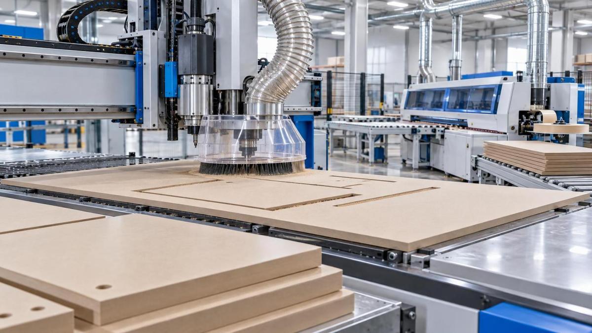
The best dust control is achieved where the cutter meets the board. On a CNC nesting machine, that normally means a hood that follows the spindle as closely as practical, together with a spoilboard and vacuum arrangement that does not allow chips to scatter across the sheet. On a panel saw, lower and upper extraction points both matter. On an edge-banding machine, trimming, scraping, and polishing stations need their own well-positioned pickup points because fine powder is generated after the primary cut as well.
There is a trade-off. Enclosures and close-fitting hoods improve capture, but they must not make tool changes, setup checks, or jam clearing unnecessarily difficult. If guards are awkward, they tend to stay open. In a real factory, a dust-control feature only works when it fits normal operating behavior.
Ductwork should be accessible for inspection. Long horizontal runs, abrupt bends, poorly sealed joints, and improvised branch connections can gradually reduce system performance. Operators may compensate by increasing machine speed or using compressed air to clear residue—both habits often make the underlying problem worse. Compressed air is particularly poor as a routine cleaning method around MDF machinery because it redistributes fine dust into the surrounding workspace and machine internals.
Edge Quality Starts Before Edge Banding
A clean MDF edge is not merely a cosmetic preference. It affects adhesive contact, edge-band coverage, paint absorption, and the perceived quality of the finished furniture. The most common defects—fiber breakout, fuzzy edges, small chips, burn marks, waviness, and inconsistent squareness—usually begin with the relationship between board density, cutter geometry, feed rate, spindle condition, and panel support.
MDF is comparatively uniform, but it is not identical from board to board. Density can vary across a sheet and between suppliers. A tool and feed setting that leaves a sharp edge on one board may produce slight fiber lifting on another, especially around shaped profiles or tight inside radii. This is why a production setup should be validated on the actual board grade and thickness being purchased, rather than only on a sample panel supplied during machine acceptance.
Tool sharpness deserves more attention than it receives. A dull cutter does not always produce an obvious catastrophic defect. More often, it creates a slightly compressed or torn edge that appears acceptable until primer, lacquer, or an edge band highlights the irregularity. Heat buildup can also darken the edge and increase the risk of resin smearing on the tool. Replacing tools only after visible failure is usually too late for finish-sensitive products.
The feed-rate and cutter-speed balance
Higher spindle speed does not automatically mean a better cut. If feed rate, number of cutting edges, and spindle speed are poorly matched, the cutter may rub rather than cut, or remove too much material per tooth. Both conditions can damage edge appearance. The correct balance depends on the tool diameter, profile, cutter material, board specification, and machine rigidity. It should be established through controlled trials and then documented as an operating window, not treated as a fixed number for every MDF job.
Machine rigidity matters just as much on contoured work. Vibration can create a faint washboard pattern along an edge, especially when a long tool projects too far from the collet or when a panel is inadequately supported. A stable spindle, properly maintained bearings, accurate linear guides, and reliable workholding are not abstract engineering features; they show up directly in the finish quality of the edge.
From Machined Edge to Finished Edge
For laminated cabinets and customized furniture, edge banding adds another layer of control. The edge must be straight or accurately profiled, free of loose fibers, and sufficiently clean for adhesive application. Dust remaining on the panel edge can prevent consistent bonding. Excessive chipping may force the machine to remove more material during pre-milling, which can alter final dimensions or make narrow components difficult to process.
Pre-milling is often worthwhile when the preceding cutting process leaves variable edges. It creates a more consistent bonding surface, but it should not be used to mask serious upstream problems. If pre-milling must remove a large amount of material to obtain a clean edge, the saw, router, tooling, or panel support arrangement deserves investigation.
Shaped and soft-forming components are less forgiving than straight panels. Curved cabinet doors, decorative end panels, and profiled furniture parts can place different demands on tape width, panel thickness, trimming geometry, and pressure settings. A machine intended for this work should be assessed on the actual profile family, not only on a straight sample. The smallest inside radius, the narrowest panel, and the most difficult edge material are often the tests that reveal whether a configuration is genuinely suitable.
For example, the Soft forming edge banding machine ZD880S is designed for curved and shaped panel edge processing in applications such as cabinets and customized furniture. Its specified panel capability includes standard 18 mm and 22 mm edge conditions, along with oblique 25 mm processing, while supported edge-banding thickness is 0.5–0.75 mm. These figures are useful starting points, but they do not replace a profile trial. Tape behavior around curves, adhesive response, and trimming quality can change with substrate density, radius, decorative surface, and production temperature.
The ZD880S operates at a stated conveying speed of 6–8 m/min and uses 0.6–0.8 MPa working pressure. For an evaluator, those values should be read alongside compressed-air quality and available plant capacity. Moisture or contamination in the air supply can affect pneumatic reliability, while unstable line pressure can show up as inconsistent pressing or movement at critical stations. It is a small infrastructure detail that can become a recurring quality complaint.
Inspection Should Follow the Product Route
Checking one finished panel at the end of the line is not enough. Quality inspection is more useful when it follows the route of the workpiece. After sawing or routing, inspect for chipping, burn marks, squareness, and surface contamination. After pre-milling, look for a uniform substrate edge. After edge application, check bond continuity and tape position. After trimming and scraping, examine the panel under angled light; this reveals chatter marks, glue residue, and uneven transitions that frontal inspection can miss.
A simple practical distinction helps: defects that repeat at a fixed interval often point toward a rotating tool, bearing, pressure roller, or conveyor component. Defects that appear randomly may be related to board variation, dust contamination, inconsistent loading, or operator handling. This does not diagnose every problem, but it prevents teams from changing multiple settings without a clear hypothesis.
Maintenance Is Part of Quality Control
MDF lines tend to reveal weak maintenance discipline quickly. Fine dust can obscure sensors, shorten the useful interval between cleaning, and build up in moving areas that were never designed to act as storage shelves. A maintenance plan should include extraction inspections, cleaning of safety and positioning sensors, spindle and collet checks, conveyor alignment, pressure-system checks, and scheduled assessment of cutters and trimming tools.
Spare parts support also deserves attention during machinery selection. Wear components, sensors, pneumatic parts, and electrical items do not all fail on the same schedule, and an otherwise capable machine can sit idle if common replacement parts are difficult to obtain. Manufacturers with long-term woodworking experience, such as Qingdao Zhongding Machinery Co., Ltd., are typically expected to support the machine beyond delivery through technical guidance, spare-parts availability, and responsive service. Those commitments should be clarified in practical terms: documentation language, remote troubleshooting process, recommended spare list, and lead time for critical components.
The most reliable MDF processing setup is usually not the one with the highest advertised speed. It is the one where extraction capacity matches real production, tools are changed before edge quality drifts, shaped-panel capability is proven on representative parts, and operators can maintain the equipment without bypassing safeguards. When those conditions are in place, clean edges and controlled dust become routine production outcomes rather than constant corrective work.
Send Your Inquiry
We welcome your cooperation and we will develop with you.