


A successful woodworking machine layout starts with production requirements: product families, daily output, machining routes, and handling constraints. Equipment selection should follow these decisions.
For project managers evaluating machines pour menuiserie, the priority is coordinating material flow, machining sequences, extraction, and operator access within the available building and budget.
Custom dimensions and changing batch sizes make this harder. A layout must accommodate variation while protecting quality, controlling work in progress, and supporting reliable delivery.
This guide explains how to define equipment requirements, position production areas, test capacity assumptions, and reserve expansion space before installation decisions become expensive to reverse.
What Must You Define Before Placing the First Machine?
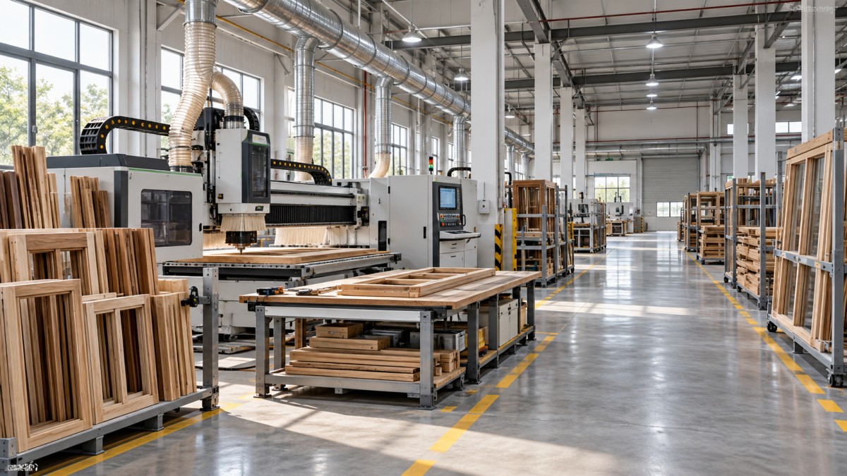
Begin with a product and capacity brief. Record door and window types, construction methods, material specifications, dimensional ranges, shift patterns, and expected daily order mix.
Distinguish solid timber frames and sashes from engineered components, panel doors, and products using purchased blanks. These choices change machining routes and equipment requirements substantially.
A workshop producing bespoke timber windows may prioritize profiling, joint accuracy, and assembly fixtures. A panel door operation may require different pressing and sizing capabilities.
Define output in finished, accepted units per shift, then translate that target into component quantities. One finished window can require several separately machined frame and sash members.
Document the most demanding recurring products, including oversized doors, deep profiles, and unusual joints. Occasional exceptions may be handled more economically through a separate process.
Agree on measurable acceptance criteria before requesting quotations: dimensional tolerances, joint fit, surface quality, changeover expectations, and the product samples used during machine acceptance testing.
This brief gives suppliers a common basis for proposals. Without it, apparently comparable quotations may assume different materials, operating conditions, staffing levels, or production scope.
How Should Materials Move Through the Workshop?
Map the actual manufacturing sequence before drawing equipment positions. A typical timber joinery route includes receiving, conditioning, rough preparation, precision machining, assembly, finishing, and dispatch.
The exact order depends on construction details. Profiling, joint machining, hardware preparation, sanding, and coating may occur at different stages for different door and window systems.
Favor a clear progression from incoming timber to finished products. Straight flow can suit long buildings, while a U-shaped arrangement may suit shared receiving and dispatch access.
Neither arrangement is automatically superior. Compare travel distance, crossing points, handling frequency, and supervision needs against the building’s columns, doors, floor condition, and structural constraints.
Separate pedestrian routes from forklift movements wherever practical. Locate unloading and dispatch areas so transport activity does not routinely interrupt machining stations or assembly work.
Give each batch an identified staging location, using carts or racks suited to component length. Avoid unplanned floor storage that gradually consumes operating and access space.
Track frame, sash, and door components by order throughout production. Clear identification reduces searching, mismatched parts, and assembly delays when several custom projects run together.
Which Machines Are Necessary, and Where Does Flexibility Matter?
Build the machine list from required operations. Depending on purchased stock condition, preparation may involve crosscutting, ripping, surface planing, thicknessing, or four-sided machining before detailed processing.
Joinery operations may require tenoning, mortising, profiling, drilling, and hardware recess machining. CNC equipment can combine selected operations when its configuration suits the intended components.
Check working dimensions and tooling access against actual product drawings. Nominal machine capacity does not establish compatibility with every profile, joint geometry, or clamping arrangement.
For frequently changing orders, setup time can outweigh cutting speed. Evaluate tool changes, program selection, fence adjustment, clamping changes, and first-piece inspection as part of production.
Dedicated machines can suit stable, repeated operations. Flexible machines become more attractive when product variety is high and programming, tooling, and operator skills are available.
Compare integrated processing against separate machines using the same representative batches. Include transfers and setups, because combining operations can also concentrate downtime at one workstation.
Request demonstrations using your materials and representative parts. Confirm acceptable joint fit, tear-out, dimensional consistency, and surface condition before committing to the proposed equipment package.
Will the Layout Deliver the Required Daily Output?
Calculate capacity at each process using available production minutes and realistic processing time. Include loading, unloading, inspection, tool changes, and the setups required by expected orders.
Use a consistent unit for comparison, such as components per shift or complete order sets. Machine cycle figures become misleading when they describe different production quantities.
For example, an eight-hour shift provides 480 scheduled minutes. If breaks, maintenance, and expected interruptions leave 360 usable minutes, base the initial capacity calculation on 360.
If a station needs three minutes per component and 45 minutes for daily setups, its calculated capacity is 105 components, before allowing for rejects or rework.
This example illustrates the method, not a production guarantee. Validate assumptions through supplier trials or observed operating data, especially where manual handling dominates the cycle.
Identify the process with the lowest effective capacity for the planned mix. It may be profiling, hardware preparation, assembly, sanding, or finishing rather than primary cutting.
Protect that constraint with reliable material supply and a controlled buffer. Buying faster upstream machines will have limited value if the limiting process remains unchanged.
How Much Space Does Each Production Area Really Need?
Machine footprints are only the starting point. Add manufacturer-required operating clearances, guarding space, maintenance access, extraction connections, and the full movement envelope of each component.
Check the longest workpiece entering and leaving each station, including turning movements. A machine that fits on a drawing may still obstruct neighboring operations during use.
Allow space for operators to handle parts safely without stepping into transport routes. Oversized doors and assembled frames may require lifting aids or additional handling personnel.
Place inspection equipment and commonly used tooling near the relevant operations. Frequent walks to shared storage can consume productive time and encourage inconsistent setup practices.
Size assembly areas around jigs, clamps, squareness checks, hardware installation, and temporary storage. Include space for completed assemblies awaiting the next process without blocking workstations.
Adhesive curing and coating drying can require substantial staging capacity. Estimate this space from throughput and residence time, allowing for racks, access, and product separation.
Test the proposed arrangement with scaled drawings or floor markings. Simulate moving the largest component and servicing key machines before approving foundations, ducts, or electrical drops.
Which Utility and Environmental Decisions Must Come Early?
Develop the extraction concept alongside the equipment layout. Duct routes, connection locations, machine requirements, and simultaneous operation affect system design, installation cost, and usable ceiling space.
Have a qualified specialist assess airflow, pressure losses, dust characteristics, and applicable fire and explosion requirements. Collector selection should follow a documented system assessment for the installation.
Keep inspection points, isolation arrangements, and maintenance access reachable. Poor access makes routine servicing harder and can undermine the extraction performance assumed during equipment selection.
Confirm electrical supply, compressed-air demand, connection positions, and installation requirements with each supplier. Include the expected simultaneous load and any capacity needed for planned expansion.
Where finishing occurs onsite, assess ventilation, coating compatibility, contamination control, and applicable separation requirements. Clean assembly and finishing areas need protection from machining dust and traffic.
Maintain material conditions appropriate to the timber, adhesive, coating, and intended service environment. Specify moisture checks and storage practices that support repeatable machining and assembly.
Coordinate emergency access, lighting, noise controls, and guarding with local requirements and competent advisers. Resolve these constraints before they force changes to an otherwise workable layout.
How Should You Compare Investment, Support, and Expansion Options?
Compare the total installed project cost, including machines, tooling, extraction, utilities, handling equipment, software, training, freight, installation, and commissioning. Identify responsibilities and exclusions in every quotation.
Assess operating cost per accepted product using realistic labor, consumables, maintenance, energy, and scrap assumptions. A lower purchase price can be offset by persistent handling or setup costs.
Estimate payback from benefits the project can substantiate: reduced overtime, fewer rejected components, lower handling effort, or additional sales supported by demonstrated capacity and demand.
Prepare a conservative case with lower demand, longer changeovers, and slower commissioning. This reveals whether the investment remains manageable when production reaches its target later than expected.
Evaluate service alongside machine specifications. Ask about technical response arrangements, spare-parts availability, documentation, training, and remote troubleshooting, with commitments confirmed for your location and equipment.
Qingdao Zhongding Machinery Co., Ltd. brings more than 20 years of woodworking machinery experience. Project discussions should translate that background into application-specific equipment and support proposals.
Reserve expansion space beside the operation most likely to become constrained. Check that future additions can connect to utilities and material routes without relocating essential production areas.
What Must Be Verified Before Production Handover?
Turn the approved layout into an installation and commissioning plan with named responsibilities. Coordinate delivery routes, unloading, positioning, utility connections, supplier attendance, and operator availability.
Define acceptance trials around representative door and window orders. Include frequent products and demanding recurring variants, with agreed materials, tooling, staffing, and measurable quality criteria.
Check the complete process from material receipt to finished assembly. Individual machine performance does not prove that transfers, identification, buffers, and inspection points work together.
Measure setup duration, processing time, handling time, first-pass acceptance, and work in progress. Compare observed results with the assumptions used to justify the project investment.
Confirm operators can perform routine adjustments, inspections, and maintenance safely. Provide accessible instructions and record any unresolved defects, missing documentation, or further training requirements before handover.
During the initial production period, review queues and delivery performance regularly. A growing buffer often signals unreliable processing, mismatched capacity, missing materials, or an unsuitable release schedule.
Use these observations to adjust staging limits, schedules, and workstation positions where practical. Retain a controlled layout drawing so subsequent changes preserve access and utility requirements.
A Practical Basis for the Final Layout Decision
The strongest layout connects product requirements, effective capacity, safe handling, and installed cost. Every major equipment position should have a clear operational reason and measurable benefit.
When comparing machines pour menuiserie, ask suppliers to validate the complete production route against your drawings, output targets, available space, utilities, and expected order variation.
Approve the investment when representative trials and documented assumptions support the plan. That discipline gives custom door and window production a stronger foundation for reliable delivery.