


News & Exhibitions
Latest Factory Updates, Industry Trends & Global Exhibition Information
Planning a Joinery Production Line for Custom Doors and Windows
Start with the range of doors and windows the line must produce, then map each component through cutting, machining, assembly and finishing. The right layout follows the workpiece: a solid-wood window sash with multiple profiles and hardware preparations places different demands on equipment and handling than a flat, veneered interior door. Capacity figures are useful only after that product mix, batch size and required quality are defined.
For a new facility or an existing ligne production menuiserie, the planning objective is a workflow that handles variation without leaving parts waiting between every operation. Establish the constraints first: the largest and smallest components, available floor space, material flow, changeover frequency and the finish required on visible surfaces.
Define the product range in components
A finished door or window is an assembly of parts with different machining routes. List the rails, stiles, frame members, glazing beads and panels separately, and identify the material and operations associated with each. Include optional features such as grooves for seals, hardware recesses, glazing rebates and decorative profiles. A schedule based only on the number of finished units can conceal the workload created by small, highly machined components.
Record the length, width and thickness ranges of each part, including allowances before final machining. Pay particular attention to short rails and narrow glazing beads: a machine that accepts the widest panel may still be unsuitable for safely feeding the smallest piece. Long frame members create a different constraint, requiring support and clearance before and after the machine.
Construction details also determine the route. A mortise-and-tenon joint requires accurate mating geometry and a dependable reference surface; a dowelled assembly introduces drilling patterns and positional tolerances. If several joint systems must run through the same line, allow for tooling changes, program selection and trial pieces rather than treating all components as equivalent.
Build the process route before choosing machines
Draw a route for each main product family, from incoming stock to packed assembly. A solid-wood route could include conditioning and stock preparation, crosscutting, ripping, planing, profiling, joint machining, sanding, assembly and coating. An engineered or panel-based door may follow a different route through panel sizing, edge processing and hardware machining. Keep alternative routes visible; forcing every part through the same stations creates unnecessary handling.
At each operation, record the incoming and outgoing condition of the part. For example, a frame member may leave a planer with a reference face and edge, then pass through profiling and end machining. If subsequent operations reference a different face, an otherwise accurate cut can produce a misaligned joint. Marking datum faces on the route sheet makes this dependency visible before fixtures and transfers are specified.
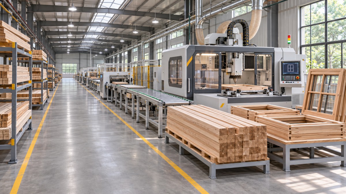
Use the route map to identify where components converge. A frame press cannot complete a batch if one rail profile is delayed at a shared machining center, even when the other parts are ready. Place temporary, clearly identified storage near these convergence points and define how matching parts are kept together. For custom orders, labels should remain legible through machining and finishing, or the identification method must change at a controlled handoff.
Size capacity around the limiting operation
Calculate the workload at each station using the number of parts, machining time and changeover time for the intended product mix. Include loading, unloading, inspection and movement where they occupy the station. Compare that workload with the productive time available per shift after planned breaks, maintenance and setup. A machine's published feed speed alone does not establish line output.
Consider a profiling station that processes long straight members quickly but needs a tooling adjustment between profiles. On a run of repeated components, feed speed may dominate. On a sequence of small custom orders, changeovers and first-piece verification can occupy more time than cutting. A flexible machining center may reduce those changes, but its cycle time across several features must still be compared with the combined workload of dedicated machines.
Test the capacity model against both a representative mix and a demanding mix. The demanding mix might contain more hardware recesses, shorter runs or a greater share of window components. If the same station becomes overloaded in both cases, it is a strong candidate for additional capacity. If the constraint moves with the order mix, routing flexibility and scheduling may be more valuable than duplicating one machine.
Buffers deserve a defined purpose and a physical limit. Space before a critical station can absorb short interruptions; an unlimited pile of unfinished parts hides delays and makes order tracking harder. Set buffer locations around actual batch sizes and material handling equipment, then confirm that aisles, access doors and maintenance areas remain clear.
Match equipment to the workpiece and finish
Machine selection starts with the full operating envelope, not just maximum working width. Verify the smallest safe workpiece, thickness range, required profile depth, tooling compatibility and the support needed for long or flexible parts. A stated maximum dimension may apply only under particular tooling or setup conditions, so the intended operation should be discussed alongside the dimension.
For custom joinery, repeatability across setups matters as much as speed during a long run. Assess how fences, stops, fixtures and programs are set and recalled. Where a part must be turned or repositioned, confirm how its reference face is maintained. Sample parts representing the smallest component, the longest member and a demanding profile are more informative than a demonstration using only an easy workpiece.
Surface treatment can add a separate operation where an exposed grain texture is specified. The Wire Drawing Machine is intended for wood surface brushing and grain enhancement. The supplied ZD1000-4 specifications list a maximum working width of 1,000 mm, a processing thickness range of 2–100 mm, a minimum length of 330 mm and frequency-controlled feed from 0 to 27 m/min. Those figures need to be considered together with brush selection, material and the required appearance; they do not establish that every door component is suitable for the machine. Short or narrow parts may need a different process or a validated holding method.
Brushing also changes downstream work. A textured surface may require a different sanding sequence and coating application from a smooth one. Trial the complete finish on representative solid wood or panel material, including edges and joints, before reserving floor space for a dedicated brushing operation.
Lay out flow around handling and access
Position stations in the order parts normally travel, while allowing branches for components that skip an operation. Avoid placing long-member machining where stock must cross the route used to move assembled frames. A compact arrangement is not automatically efficient if every transfer requires turning a large door leaf or clearing an aisle.
Show the equipment at its installed footprint and add the working envelope: infeed and outfeed length, loading side, tooling access, extraction connections and maintenance clearance. Draw the longest workpiece in position, not just the machine outline. For presses and assembly tables, allow room for fixtures, clamps and the movement of completed frames without placing pressure on fresh joints.
Separate clean and dusty stages as the building permits. Machining and sanding generate dust that can affect coating quality; the layout should account for extraction, transfer routes and the condition in which parts enter finishing. Confirm electrical supply, compressed air where required, dust extraction and any finishing ventilation against the selected equipment and facility design before installation positions are fixed.
Control fit at the points where parts meet
Quality checks are most useful before an error is multiplied across a batch. After setup, verify a sample against the drawing and assemble mating pieces where practical. A joint that measures correctly on an individual part can still fit poorly if its mating feature uses a different reference or if accumulated variation changes the frame dimensions.
For windows, verify the relationship between frame, sash, glazing rebate and seal grooves as an assembly. Hardware preparation should be assessed against the actual hardware layout, including handed parts. For doors, confirm finished dimensions and the position of lock, hinge and other recesses after the operations that establish the final edges. Changes to a profile or hardware specification must reach both the machining program and the inspection record.
Material condition affects these checks. Solid wood can change dimension with moisture and may move after material is removed; engineered materials have their own surface and core characteristics. Define the material condition at receipt and before precision machining, and investigate recurring fit variation before compensating solely through machine offsets.
Commission the route with real orders
Before production starts, verify machine alignment, guarding, extraction, controls and emergency stops as part of the installation process. Then run representative components through the connected route, including identification, transfer, assembly and finishing. Record actual setup and cycle times, the amount of work waiting between stations, and any damage or rework caused by handling.
A successful individual machine test does not prove that the line works as a system. Trial at least one order with frequent size or profile changes and another with a longer repeated run. Compare the results with the capacity model, adjust routing or buffer locations where needed, and retain the approved settings and inspection results for repeat work.
Leave room for growth where the route is most likely to change: access to a shared machining station, a finishing queue or an assembly area may matter more than unused space at the end of the building. Any future addition should preserve safe access and the established flow of identified parts.
Send Your Inquiry
We welcome your cooperation and we will develop with you.