


News & Exhibitions
Latest Factory Updates, Industry Trends & Global Exhibition Information
Industrial Woodworking Equipment: Core Machines for Panel Processing
Industrial woodworking equipment for panel processing centers on three operations: cutting sheets into accurate components, finishing exposed edges, and machining holes or joints for assembly. Panel saws and CNC nesting routers handle sizing; edge banding machines cover and finish panel edges; drilling machines produce the connection points. Sanding and material handling equipment support these operations where the material and production sequence require them.
The right combination follows the parts being produced. Straight cabinet components, shaped furniture panels, and unfinished veneered boards place different demands on a workshop. Machine specifications become useful only when connected to panel dimensions, surface quality, batch size, and the way parts move between operations.
Start with the panel and its route through production
Melamine-faced particleboard, MDF, plywood, and veneered panels behave differently during machining. A brittle decorative face needs support at the cutting edge to limit chipping. MDF produces fine dust and requires effective extraction. Plywood introduces changes in grain direction and possible internal voids, while veneered surfaces require care to avoid damage to the thin decorative layer.
A common cabinet production route begins with sheet cutting, followed by edge banding, drilling, and assembly. CNC nesting changes that sequence: a router can cut component outlines and machine face holes or grooves while the sheet remains on the table. Horizontal holes in panel edges generally require another operation unless suitable aggregates or additional equipment are available.
This distinction affects equipment selection. A machine described as capable of “cutting and drilling” does not necessarily complete every hole required for a cabinet. Face holes, edge holes, hinge recesses, and connector pockets involve different tool access and workholding requirements.
Part identification also belongs in the workflow. Once a sheet becomes a stack of similar rectangles, orientation mistakes become easy. Labels or consistent marking should preserve the relationship between the part, its finished edges, grain direction, and drilling program.
Panel saws: accurate rectangular parts at the cutting stage
A sliding table panel saw provides a flexible starting point for straight cutting. The moving table supports the panel as it passes the blade, while fences establish dimensions and angles. Finished accuracy depends on machine alignment, blade condition, panel support, and consistent contact with the reference fence.
On faced boards, a scoring blade makes a shallow cut through the underside surface before the main blade completes the cut. Its width and alignment must match the main blade’s cutting path. An incorrectly adjusted scorer can leave a visible step or fail to prevent underside chipping. A clean upper face alone therefore does not establish that the cutting setup is correct.
A beam saw, also called a pressure beam panel saw, uses a controlled pusher and clamping beam to position and secure material during cutting. It suits repeated rectangular cutting patterns and organized sheet processing. Stack cutting increases output only within the machine’s capacity and the material’s stability; movement between sheets or inconsistent thickness can affect results.
Nominal cutting capacity deserves careful interpretation. Maximum cutting height describes a physical limit, while achievable edge quality also depends on blade geometry, feed conditions, sheet construction, and the number of panels in the stack. Likewise, a high positioning speed does not describe the time needed to load sheets, turn strips, remove parts, and sort components.
CNC nesting routers: combining profiles and face machining
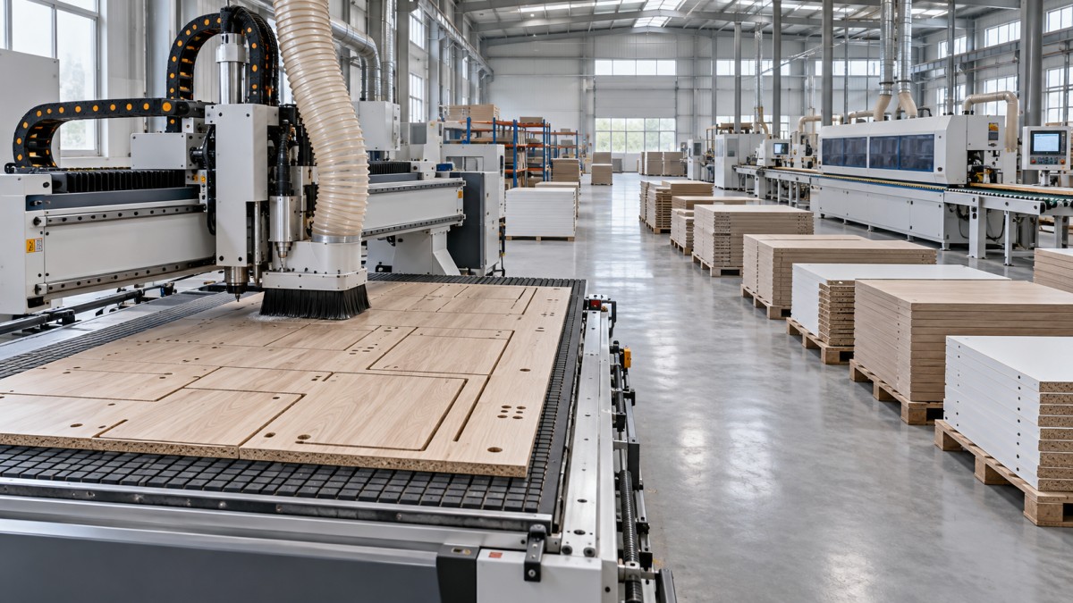
A CNC nesting router holds a sheet on a vacuum table and uses programmed toolpaths to cut components. Its advantage becomes clear when parts include curves, cutouts, grooves, or multiple face-machining features. Rectangular cabinet parts can also be nested, although the practical balance against a panel saw depends on the complete production route.
Tool diameter creates space between nested parts, and every routed perimeter requires machining time. A nesting layout with attractive material utilization may still produce a long cycle if it contains many small components or extensive contours. Sheet yield and finished parts per shift measure different things.
Vacuum hold-down needs particular attention as components become smaller. Cutting separates parts from the surrounding sheet and changes the available holding area. A porous spoilboard, blocked vacuum zones, leakage, or dust beneath the sheet weakens restraint. Small parts require a suitable cutting strategy, such as leaving a thin bottom layer for a final pass or using tabs where subsequent removal is acceptable.
Spindle power alone is an incomplete comparison. Tooling, acceleration, vacuum performance, tool changes, and program structure all affect productive cutting. Compression cutters can protect both faces of laminated panels when the cutting depth correctly engages their opposing cutting sections; unsuitable engagement can still leave one face damaged.
The software connection matters just as much as the mechanics. Part dimensions, tool compensation, machining faces, and labels must transfer correctly from design data to the machine program. A consistently misplaced hole often points toward a reference or programming issue rather than random mechanical inaccuracy.
Edge banding: where cut quality becomes visible
An edge banding machine applies edging to the exposed core and finishes it to the panel surface. Depending on configuration, the process includes pre-milling, adhesive application or functional-layer activation, pressure rollers, end trimming, top and bottom trimming, scraping, and buffing. These stations have separate jobs, and their presence should not be assumed from the machine’s overall size.
Pre-milling removes a small amount of material from the cut edge to establish a clean bonding surface. It can correct limited cutting defects, but the removed allowance must be included in the part dimensions. Feeding an already finished-size panel through an unaccounted pre-milling operation changes its final size.
Conventional hot-melt systems apply adhesive between the board and edge tape. Laser systems activate a compatible functional layer on the edging. Ordinary PVC edging is not automatically suitable for laser processing: the tape construction and activation requirements must match the equipment. The term “zero-joint” describes the intended visual result; it does not remove the need for accurate preparation and process control.
The Laser Edge Banding Machine ZD450F illustrates the specifications that need to be read together. Its stated ranges include a feed speed of 10–23 m/min, panel thickness of 10–40 mm, edge tape thickness of 1.0–3.0 mm, and minimum panel width of 60 mm. These figures define separate parts of the processing envelope; they do not establish that every combination of tape, panel, and speed produces the same finish. Laser-compatible edging and the intended board material still require a suitable process setup.
Feed speed also needs to match the finishing stations and component spacing. Short parts, thick edging, corner rounding, and demanding surface finishes affect usable throughput. A quoted maximum feed speed says little about the number of completed components leaving the machine during a mixed production run.
Similar-looking edge defects can have different causes. A visible joint can result from poor edge preparation, unsuitable activation or adhesive conditions, or insufficient pressure. White marks on dark edging may originate at trimming or scraping. Diagnosing the station responsible avoids changing bonding settings to correct a finishing problem.
Drilling equipment: keeping assembly references consistent
Drilling machines create shelf-pin holes, hinge cup recesses, dowel holes, and fittings for panel connectors. Multi-spindle boring machines perform repeated hole patterns efficiently when dimensions remain consistent. CNC drilling centers accommodate changing patterns through programmed positioning and, on suitably configured machines, machining from several directions.
The important question is which faces and edges the machine reaches in the intended setup. A vertical drilling capability does not imply horizontal edge drilling. Tool count also needs interpretation: several spindles arranged for one repeated pattern provide different flexibility from independently selected tools working across multiple surfaces.
Assembly accuracy depends on a shared reference system. If cutting dimensions are referenced from one edge and drilling positions from another, edge band thickness or an incorrectly oriented part can shift the final connection. Drawings and programs should distinguish the raw core dimension from the finished external dimension wherever edging affects hole placement.
Hole quality is separate from hole position. Worn drills, unsuitable feed, poor backing, or chips trapped at the clamping surface can cause breakout or inconsistent depth. When mating parts fail to align, measuring the panel size, reference edge, hole position, and hole depth separately narrows the cause.
Sanding belongs where the surface requires it
A wide belt sander is relevant when panels need thickness calibration or surface preparation before finishing. Solid wood panels, unfinished veneers, and coated components introduce different sanding requirements. Factory-finished melamine panels generally do not pass through abrasive sanding as part of routine cabinet sizing and edging.
Calibration removes material to control thickness; finish sanding prepares surface texture. These tasks place different demands on the contact roller, sanding platen, abrasive sequence, and removal amount. A fine abrasive does not correct substantial thickness variation efficiently, while aggressive calibration risks cutting through a thin veneer.
Panel thickness consistency also affects downstream processes. Pressure systems and trimming tools respond to the surfaces passing through them, so uneven material can create edge finishing variation even when machine settings remain unchanged.
Compare the production cell, including its constraints
The most useful equipment comparison follows representative parts through the full sequence. A large rectangular side panel tests different capabilities from a narrow rail or a small shelf. Including the smallest component, the most demanding surface, and the main connector pattern exposes limitations that a simple demonstration panel can conceal.
Dust extraction, compressed air, and floor space directly affect machine performance. Fine dust interferes with vacuum sealing and clean reference surfaces. Air pressure at the supply point does not establish adequate flow during simultaneous machine operation. Equipment dimensions also exclude the space needed for sheet loading, long-panel travel, access to tooling, and maintenance.
A practical acceptance trial uses the intended panel material, edging, and machining data. Parts should be measured after the relevant operations and assembled with the intended fittings. Record the settings alongside the results: a clean edge, accurate hole pattern, and correctly fitting joint are most useful when the conditions that produced them can be repeated.
Send Your Inquiry
We welcome your cooperation and we will develop with you.