


News & Exhibitions
Latest Factory Updates, Industry Trends & Global Exhibition Information
How to verify cut straightness on a precision single blade rip saw
How to verify cut straightness on a precision single blade rip saw
A clean-looking rip cut is not always a straight one. Fine tooth marks can hide a gradual bow, while a rough edge may still follow a straight line. That distinction matters when boards move directly into edge gluing, panel assembly, or another operation with little machining allowance.
Verifying cut straightness on a precision single blade rip saw requires more than placing two boards together and looking for daylight. A useful inspection separates edge geometry from surface finish, controls how the timber is supported, and records when the measurement was taken. Otherwise, timber movement can be mistaken for machine error—or a feeding problem can be dismissed as “just the wood.”
Define the acceptance rule before making the test cut
Start with the downstream requirement. A rip-cut edge intended for immediate gluing may need a different acceptance limit from an edge that will be jointed afterward. There is no defensible universal straightness tolerance simply because a machine is described as “precision.” Use the purchase specification, approved production drawing, manufacturer’s acceptance procedure, or an agreed internal inspection requirement.
The requirement should identify the inspection length, measurement method, allowable deviation, and whether the entire edge or a defined working length is assessed. If the leading and trailing ends are excluded, state that explicitly. Quietly ignoring an entry defect changes the test rather than improving the result.
Also distinguish three different characteristics: straightness along one edge, width consistency between opposite edges, and squareness of the sawn face to the board face. A board can have straight edges but taper in width. It can also be straight at its upper edge and bevelled through its thickness.
Choose stock that tests the saw, not just the timber
For a baseline check, select sound, reasonably stable material with a flat supporting face and a suitable guiding edge where the machine design requires one. Avoid obvious twist, loose knots, splits, and severe grain distortion. Use stock within the manufacturer’s permitted dimensions, with enough material removed to establish a continuous new edge.
A narrow, stressed strip is a poor baseline specimen: it may bend immediately after being released from the parent board. Conversely, testing only short, easy pieces can conceal errors that appear over normal production lengths. Establish the baseline with manageable stock, then confirm performance using representative production material, including relevant thicknesses and lengths.
Mark each specimen with its feed direction, supporting face, cut-edge identity, and test sequence. Record species or material type, dimensions, moisture condition where relevant, blade identification, and feed setting. Preserve the initial setup details; they become valuable if the results change after an adjustment.
Keep inspection separate from the cutting operation
Make trial cuts only with guards, extraction, anti-kickback provisions, and feeding equipment correctly installed and functioning. Follow the machine manual for safe stock dimensions and operating positions. Do not bypass a guard to watch whether the board is tracking straight, and do not reach into the feed path to correct a suspect cut.
Before inspecting or adjusting the blade, arbor, pressure devices, chain, tracks, or internal guides, isolate all relevant energy sources under the site’s lockout procedure. Account for stored pneumatic or hydraulic energy and wait for complete blade stoppage. A stopped motor is not, by itself, proof that the machine is safely isolated.
Routine edge measurement belongs on a separate inspection bench. If a trial produces binding, abnormal noise, unstable feeding, or evidence of kickback, stop the test. A dimensional inspection is not a reason to continue operating an unsafe setup.
Measure against a reference you can trust
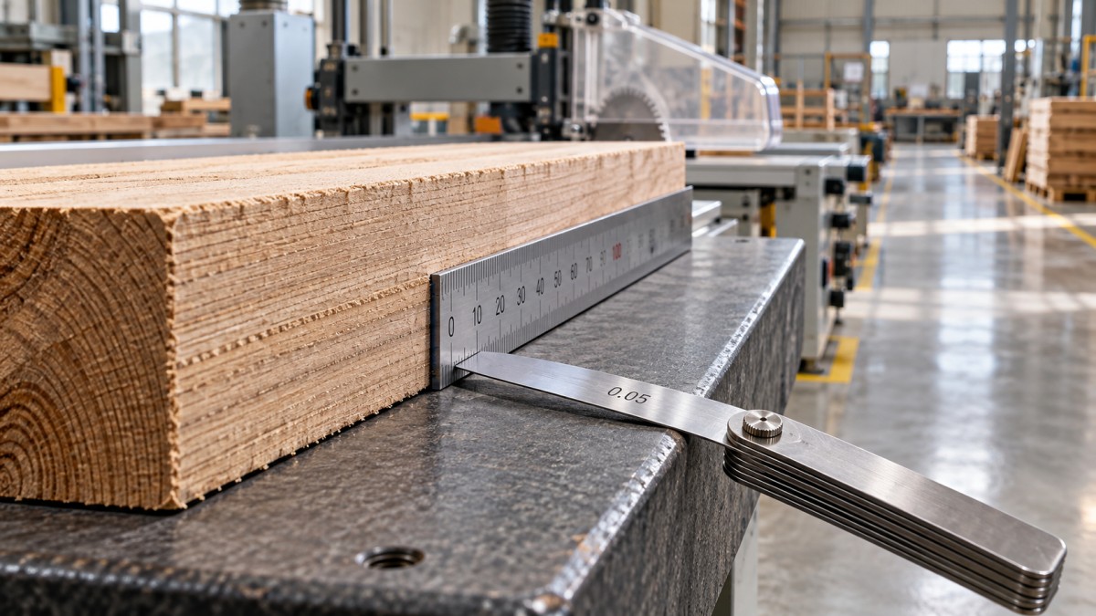
For a practical workshop check, use a verified precision straightedge covering the agreed inspection length, together with suitable feeler gauges. A spirit level, fence extrusion, or neighbouring board is not automatically a straightness reference. The reference’s error and the gauge resolution must be small enough to support the acceptance decision.
Clean both surfaces before measuring. Remove loose dust and fibres without sanding or jointing the test edge. Support the board on a stable bench without forcing it flat or straight. Long or flexible specimens need a consistent support arrangement; excessive clamping can make a bowed edge appear acceptable.
Place the reference along a defined line on the sawn face, avoiding damaged corners. Check near both ends and at several intermediate positions. On thick material, repeat near the upper and lower portions of the face to expose differences through the cut depth. Record where the largest deviation occurs, not just its size.
For a concave edge, the reference may bridge the ends and leave a measurable central gap. Insert feeler gauges gently; wedging them into the gap can move the reference or compress wood fibres. For a convex edge, the straightedge may rock on a central high point. Measuring one end gap in that unstable condition is not a reliable straightness result.
If the edge is convex, irregular, or close to the acceptance limit, use a controlled profile-measurement setup rather than improvising. A dial indicator travelling on an independently verified straight guide can map lateral edge position, provided the fixture does not distort the board and the contact force is suitably low.
In that setup, establish the specified reference line and record signed offsets along the inspection length. If using an endpoint chord, subtract the line joining the endpoint readings from the measured profile. Clearly label the result as an endpoint-chord measurement: it is not automatically equivalent to a minimum-zone straightness evaluation. Acceptance data must use the same definition as the specification.
Keep surface texture in perspective. An indicator tip dropping into individual tooth marks can exaggerate the apparent profile, while a broad contact can bridge local defects. Use a consistent contact arrangement and document whether the inspection concerns overall bow, local waviness, or both.
Repeat the check before blaming alignment
One board is a clue, not a diagnosis. Cut a small series under unchanged conditions and compare the shape and location of the deviations. For a borderline result, remove and reposition the same specimen, then measure again. A second inspector can help reveal inconsistent reference placement or gauge pressure.
Measure promptly after cutting and, where movement is suspected, repeat after a defined interval under recorded storage conditions. A profile that changes after cutting suggests stress release or moisture-related movement, though it does not prove that the machine is faultless. Record the elapsed time rather than describing both readings as “after cutting.”
Two-edge comparison is useful as a quick production screen, but not as the sole acceptance method. Matching curves may nest together, and forcing a joint closed hides the unloaded geometry. For glue-joint work, judge both the measured edge and the fit under the actual approved assembly process.
Read the error pattern without overdiagnosing it
A repeatable curve on several stable specimens warrants checking the relationship between the blade cutting plane and the feed path. Depending on the design, this may involve the chain or belt track, guiding components, pressure system, table condition, or fence. Use the manufacturer’s alignment datums; do not adjust everything until the cut happens to improve.
- Deviation concentrated at entry or exit: investigate stock support and how the workpiece is controlled as it engages or leaves the feed system.
- Periodic waviness: investigate feeding irregularity, blade condition, vibration, and rotating-component issues. The pattern alone does not identify the defective part.
- Acceptable light cuts but poor production cuts: examine cutting load, blade suitability, sharpness, feed setting, and pressure settings within the manufacturer’s permitted range.
- Results varying mainly between boards: examine timber stability, supporting-face quality, and guidance consistency before changing machine geometry.
Burning deserves separate attention. It may accompany rubbing, poor chip clearance, an unsuitable feed condition, or alignment problems, but it is not a straightness measurement. Likewise, blade runout is a component condition to investigate, not a substitute for checking the finished edge.
Make the result useful for maintenance and release
A useful inspection record connects the result to the setup: machine identification, blade, feed conditions, specimen details, support arrangement, reference equipment, measurement positions, elapsed time, and acceptance rule. Include a simple profile sketch or readings where possible. “Cut not straight” gives maintenance very little to work with.
For manufacturer support, that evidence is more useful than a photograph of daylight alone. Qingdao Zhongding Machinery Co., Ltd., a woodworking machinery manufacturer and exporter with more than 20 years of industry experience, provides technical support and spare-parts assistance. When requesting help, identify the exact machine and its configuration so the inspection can be related to the correct feed system, adjustment points, and replacement components.
After a correction, repeat the original test before changing other variables. Then confirm the result on representative production stock. Release the precision single blade rip saw against the agreed measurement rule—not because the latest edge looks smoother or because two pieces can be pushed together. If the result remains too close to the limit for the measuring method to resolve confidently, improve the measurement before declaring the machine acceptable.
Send Your Inquiry
We welcome your cooperation and we will develop with you.