


News & Exhibitions
Latest Factory Updates, Industry Trends & Global Exhibition Information
How to set up a woodworking tenoning machine for repeatable tenon shoulders
A tenon shoulder becomes repeatable when the machine is referenced from one stable baseline and every adjustment is made in the correct order. The shoulder is not controlled by the cutter alone. It is the result of fence position, workpiece support, cutter height, material registration, and the way the stock is presented to the machine.
On a Woodworking Tenoning Machine, a small shift in any one of these settings can produce parts that look nearly identical but assemble differently. One rail may sit proud of the stile, another may leave a visible gap, and a third may pull the frame out of square during clamping. The practical goal is not simply to cut a tenon that fits. It is to establish a setup that produces shoulders which locate every workpiece in the same position, across the full batch.
Start by defining the shoulder datum
Before moving a fence or installing a cutter, decide which face and edge of the component will be the reference surfaces. In frame construction, this is commonly the show face and the edge that controls the finished width. Mark them consistently before machining. If some parts are referenced from the opposite face, shoulder lengths may vary even when the machine has not moved.
This point is especially important with stock that is not perfectly uniform. Planed parts can still vary slightly in thickness, and parts may carry a small amount of twist or bow. A tenoning setup can only repeat its reference. It cannot correct inconsistent material preparation.
Machine all parts with the same reference face against the table, carriage, or locating support, depending on the machine design. Keep the reference edge against the same fence surface. Do not turn parts over merely because handling seems easier; that creates a second datum and introduces another source of variation.
Prepare stock before setting the machine
Repeatable shoulders begin upstream. Cut components to a controlled length, joint or machine the reference edges, and inspect for bow, twist, or loose knots near the tenon area. A warped part can rock on the sliding table or against a support fence. The cut may be accurate relative to the machine, while the shoulder is inaccurate relative to the part.
For a production run, sort the stock before setup. If material thickness varies noticeably, either correct it before tenoning or separate it into groups. Trying to make one cutter setting serve widely different material thicknesses usually creates uneven cheek thickness and poor joint fit.
Square the machine references before chasing the cutter setting
A common mistake is to adjust the cutter repeatedly when the real problem is a fence that is not square to the direction of feed. On a sliding-table tenoner, the crosscut fence, carriage stop, and workpiece clamp establish the shoulder position. On a fixed-table machine, the work holder and feed reference perform the same role. Check these references first.
With the machine isolated from power, clean the table, carriage tracks, fence faces, and locating stops. Fine chips or hardened resin under a fence block can move its position enough to affect a close-fitting joint. Confirm that the fence locks without creeping and that the stop does not shift when the workpiece is pressed against it.
Use a reliable square to check that the fence is perpendicular to the feed direction. Then check it with a straight sample board, not only with a measuring tool. Place the board against the fence, slide it through the normal travel path, and watch for movement away from the fence face. A fence can appear square at one point but change relationship as the carriage moves if the mounting or sliding mechanism has play.
For parts with a haunch, stub tenon, or different shoulder locations at each end, establish which stop controls each operation. Clearly identify the stop positions rather than relying on a scale alone. Machine scales are useful for returning close to a known position, but a test piece determines the final setting.
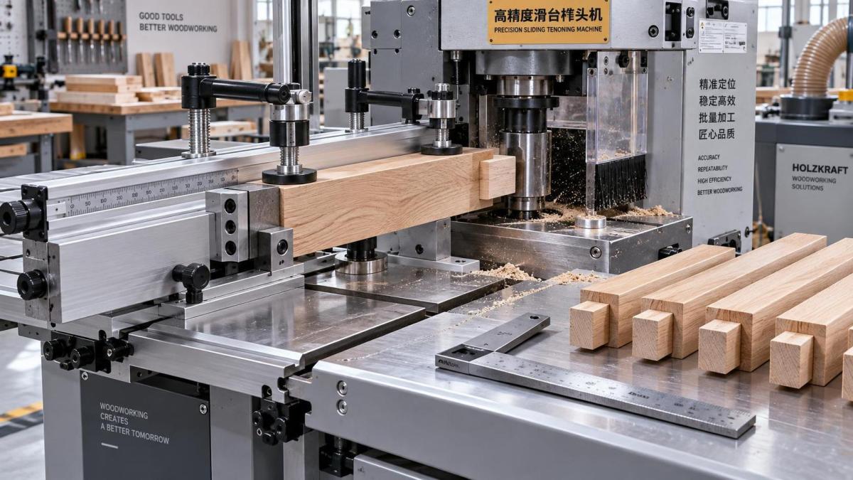
Set the cutter stack to the joint, then set the shoulder stop to the part
The cutter arrangement controls tenon length, cheek thickness, shoulder depth, and any groove-related features. The stop or fence controls where that arrangement meets the workpiece. Treat these as separate tasks. If they are adjusted together without a sequence, it becomes difficult to identify what caused a dimensional change.
Install the correct tooling for the joint design and ensure that all cutter blocks, spacers, collars, and arbor hardware are clean and seated correctly. A trapped chip, damaged spacer, or improperly seated cutter can cause runout. That may show up as a shoulder that is rough, stepped, or inconsistent from one pass to the next.
Set cutter height using the chosen reference face. For a centered tenon, the usual aim is to leave balanced cheeks, but the tenon does not always need to be centered. A face-referenced tenon may be intentional when one face must remain flush in the finished assembly. What matters is that the cutter height matches the joint drawing and that every component is presented from the same datum.
Next, set the lengthwise shoulder position with the stop or fence. It is useful to think of the process this way: the cutter defines the shape of the tenon; the stop determines where the shoulder falls. Measure from the actual reference end of the sample, not from an assumed edge that may be trimmed later.
Lock the adjustment only after the setting has been verified by a test cut. Hand pressure against a stop can reveal a weak lock or a stop block that flexes. If the stop moves under normal loading, tightening the cutter adjustment will not solve the problem.
Use test cuts to diagnose, not just to approve
Make the first test cut on stock with the same species, thickness, and preparation as the production material. Offcuts are acceptable only if they share the same reference surfaces and dimensions. A test piece from thinner or flatter stock may give a misleading result.
Check shoulder accuracy in two ways. First, measure from the part end to the shoulder at both edges of the face. Second, place the tenoned part against its mating component or a straight reference surface. A shoulder can have the correct nominal length and still be out of square, producing a gap at one side of the joint.
Change only one variable between tests. If the shoulder is too long, adjust the shoulder stop by the required amount and cut another sample. Do not change fence position, cutter height, clamp arrangement, and feed technique at once. Multiple simultaneous changes may produce a better-looking sample by chance while leaving the setup unstable.
Once the shoulder position is correct, cut several consecutive test pieces. This is more revealing than approving a single part. Compare their shoulder dimensions and dry-fit them into representative mating parts. A setup that produces one good test piece but drifts over several cycles needs attention before production begins.
Workpiece holding determines whether the setting survives production
Tenoning cutters generate side force. If the stock shifts even slightly against the stop, the shoulder location changes. If it lifts from the table, the cheek position changes as well. The workpiece must be restrained against the locating surfaces without being distorted by excessive clamping force.
Set clamps so they press the workpiece firmly onto the table and into the fence, while keeping hands clear of the cutting zone. Long, narrow rails need support close enough to prevent rocking, especially when the tenon is being formed near the end. A support extension or auxiliary fence can help maintain the same contact condition from the first piece to the last.
Do not rely on hand pressure as the primary registration method for repeat work. Hand pressure varies with operator position, stock weight, and fatigue. It may be acceptable for a carefully controlled one-off operation on suitable equipment, but it is not a dependable basis for repeatable batch work.
For short components, use an approved holding fixture or carrier designed for the machine. Small pieces are harder to register securely and can be unsafe to feed directly. The fixture should reference the same surfaces used by the production setup. A fixture that introduces its own offset requires a separate verified setting.
Control the cut sequence for clean shoulders
The order of operations affects both accuracy and appearance. On many tenoning machines, operators make a shoulder-forming pass and then form the cheeks, although the suitable sequence depends on the cutter configuration and joint design. Follow the tooling arrangement and machine procedure intended for the operation rather than improvising the sequence.
Where a shoulder cut is prone to breakout, a light scoring action or an appropriate cutter arrangement can improve the edge quality. However, a cleaner shoulder should not be confused with a more accurate shoulder. Finish quality and location accuracy must both be checked. A sharp cutter may hide a registration problem because it leaves a crisp line in the wrong place.
Keep feed pressure steady throughout the pass. Hesitation does not usually alter a securely fixed mechanical stop, but it can affect surface quality and may encourage the operator to reposition the part. Feed changes can also expose vibration, insufficient clamping, or a cutter that needs servicing.
Build a setup record that can actually be repeated
When a joint is proven, record more than a fence scale reading. A useful setup record includes the joint name, reference face and edge, cutter stack arrangement, spindle or cutter height reference, stop location, clamp or fixture arrangement, and the measured results from the approved test piece. A photo of the cutter stack and stop arrangement can prevent errors when the setup is repeated later.
Keep a labeled master sample if the work is repeated regularly. It gives a direct physical comparison for shoulder position, tenon thickness, haunch location, and overall fit. The master sample should be protected from damage and identified clearly; an unmarked offcut soon becomes unreliable.
Scales and digital readouts reduce setup time, but they do not eliminate test cuts. Tool changes, maintenance, different cutter assemblies, and material variation can all alter the final result. The most efficient routine is usually to return the machine close to the recorded position, make a controlled sample, make the smallest required correction, and then lock the setup for the batch.
When the shoulders still will not repeat
If the machine produces changing shoulder lengths after the fence and stop have been checked, look for mechanical movement rather than continuing to compensate with settings. Inspect fence locks, stop blocks, carriage bearings or slides, clamp hardware, arbor seating, and table cleanliness. Also inspect the stock ends. A poorly squared end can make a correctly located shoulder appear inconsistent when measured from the corner.
Problems that appear only with longer components often point to inadequate support or stock bow. Problems that appear only after a tool change often point to cutter stack assembly, arbor seating, or a different effective cutter width. Problems that appear at both ends of a frame component may come from switching reference faces between operations.
Machine capability matters here. A rigid table, stable sliding system, repeatable stops, suitable clamping, and correctly maintained tooling make setup easier to hold. Qingdao Zhongding Machinery Co., Ltd. supplies woodworking machinery alongside technical support and spare-parts service, which can be relevant when a workshop needs to maintain repeatability over extended production rather than solve a single setup issue.
The final check is the assembly, not only the rule. Cut several parts, dry-fit them with their mating pieces, and inspect the shoulder lines from the visible face. When the joints close without forcing, the faces remain flush, and the shoulder lines align across consecutive assemblies, the setup is ready to run. Preserve the reference method and the physical conditions that created that result; those are what make the next batch repeatable.
Send Your Inquiry
We welcome your cooperation and we will develop with you.