


News & Exhibitions
Latest Factory Updates, Industry Trends & Global Exhibition Information
How planer feed speed affects solid wood surface quality
How Planer Feed Speed Affects Solid Wood Surface Quality
In solid wood machining, feed speed is often treated as a production setting: faster feed means more boards per shift, while slower feed means more time at the machine. That view is incomplete. On a planer, feed speed is one of the variables that determines how the cutting edge meets the wood fibre, how visible knife marks become, whether a surface is ready for finishing, and how consistently a line can hold quality from one batch to the next.
For quality control and safety teams, this matters because surface defects rarely remain isolated defects. A rough or torn surface may require additional sanding, create unstable stain absorption, expose weak grain around joints, or trigger rework after downstream assembly has already started. Operators may also respond to poor output by making unsafe adjustments near moving components, increasing pressure on feed systems, or running material that should have been rejected because of warp, knots, embedded grit, or moisture-related movement.
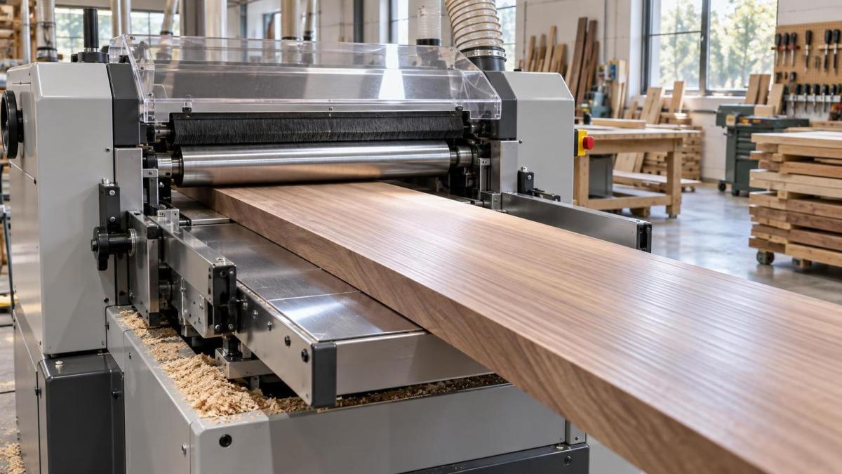
A well-configured Solid Wood Planing Machine can provide a broad usable operating range, but it cannot remove the basic relationship between feed speed, cutterhead speed, knife geometry, wood species, and material condition. Good results come from controlling the whole cutting system rather than treating feed speed as a single “quality” button.
The practical link: feed per knife mark
The most direct effect of feed speed is on the distance the board travels between consecutive knife cuts. This distance is commonly called feed per tooth, feed per knife, or knife-mark pitch. In simplified terms, it is determined by feed speed divided by cutterhead rotational speed and the number of effective cutting edges.
When feed speed rises while cutterhead speed and knife count remain unchanged, each cutting edge removes material farther apart along the board. The result is a larger scallop pattern. On some rough-stock operations, this may be acceptable. On visible furniture parts, cabinet doors, table components, flooring, or pre-finishing stock, it can become obvious under side lighting, clear coatings, or dark stains.
The opposite is also true: reducing feed speed generally decreases the spacing between marks and can improve the apparent smoothness of the surface. Yet a slower feed does not automatically guarantee a better board. If knives are dull, misaligned, contaminated with resin, or poorly set, slowing the feed may simply produce more burnishing, fibre compression, or repeated rubbing. Quality teams should therefore distinguish between a regular machining pattern caused by a feed-speed decision and an irregular defect caused by a cutting or machine-condition problem.
A useful inspection habit is to look at the board under raking light rather than only from directly above. Regular, evenly spaced lines tend to point toward cutterhead and feed relationships. Random ridges, alternating deep marks, or isolated gouges often indicate something else: a damaged knife, runout, vibration, loose pressure elements, contamination, or unstable material movement.
Why surface smoothness is not the same as surface integrity
A board can feel smooth to the hand and still be unsuitable for finishing. This is particularly important with solid wood because grain direction changes within the same piece, around knots, through figured grain, and near areas of growth stress. A planer may leave a visually clean surface on straight grain but pull fibres below the surface where grain rises into the cutter. After stain, sealer, or topcoat is applied, that hidden damage can become much more visible.
Higher feed speed increases the mechanical demand on the cutting edge. Where grain is difficult, the knife has less opportunity to make a clean shearing cut and may lift or break fibres instead. This is one reason tear-out often appears suddenly when production is accelerated, even if the same setup ran acceptably at a lower rate. It is not always a sign that the machine is underpowered. Often, it is a mismatch between feed rate and the particular wood being processed.
Species matters, but board-to-board variation can matter just as much. Dense hardwoods may resist cutting forces and show knife marks clearly. Softwoods can compress under pressure and later recover, making defects harder to judge immediately. Interlocked grain, highly figured stock, short pieces, reclaimed timber, and boards with changing moisture conditions require more cautious settings. A speed that is reasonable for straight-grained stock should not be assumed safe for every incoming bundle.
The direction of feed relative to grain
Feed speed cannot compensate fully for an unfavorable grain direction. Whenever possible, material should be fed so the cutter works “downhill” with the grain rather than lifting fibres. In real production, that is not always practical; components may have mixed grain, and four-sided processing may restrict orientation choices. In those cases, lower feed speed, sharper knives, reduced stock removal, and appropriate cutterhead design become more important.
There is also a quality-control implication here. If tear-out is concentrated on one end or one face of a part, do not assume the solution is simply to slow the line. Check whether material is consistently being introduced in the wrong direction, whether operators are mixing face orientation, or whether the board contains a local grain reversal. A defect map by board position can reveal more than a general complaint that “the planer finish is rough.”
Feed speed changes the load on the entire machine
At higher feed speeds, a planer is not only making wider-spaced cuts. The feed system must control the workpiece more firmly and consistently. Feed rollers, pressure shoes, beds, side guides, and anti-kickback devices have to maintain stable contact without crushing, slipping, or allowing the board to bounce. If the workpiece moves unevenly through the cutterhead, the result may be chatter marks, snipe, thickness variation, or a repeating pattern that operators mistake for normal knife marks.
Snipe deserves particular attention because it is frequently accepted as an unavoidable planer issue when it is often a setup or maintenance signal. Excessive entry or exit snipe may relate to insufficient support, improper pressure settings, worn tables, roller adjustment, inconsistent stock thickness, or a board that is too short for stable control. Increasing feed speed can make an already marginal condition more apparent. Slowing down may mask it temporarily, but the better response is to identify why the workpiece is not being supported correctly.
Vibration is another common source of false diagnosis. A machine may produce a repeating surface defect that resembles a feed-related scallop, but the actual cause can be imbalance, bearing wear, inadequate foundation support, loose cutterhead components, or a damaged insert. Before changing production targets, maintenance and quality personnel should compare the defect spacing with cutterhead-related patterns and inspect the machine under lockout conditions.
A fast line can be stable; an unstable line is the real problem
There is no universal “correct” feed speed for solid wood planing. The appropriate setting depends on the required finish, cutterhead configuration, number of cutting edges, spindle speed, depth of cut, wood condition, component dimensions, and the capacity of the feed mechanism. A high-output line can deliver excellent quality when its cutterhead, tooling, stock preparation, and process controls are designed for that output. Conversely, a low feed rate can still produce poor surfaces if setup discipline is weak.
The operational mistake is to change feed speed without defining what quality condition is being protected. A production supervisor may ask for a faster rate to reduce backlog. Quality may ask for a slower rate after finding tear-out. Neither instruction is complete unless the team agrees on acceptance criteria: visible knife marks under specified lighting, permitted tear-out area, thickness tolerance, edge condition, finish readiness, or sanding allowance.
For parts that will receive opaque paint, a slightly more pronounced machining pattern may be economically acceptable if downstream sanding removes it reliably. For clear-finished hardwood components, the same pattern could be a rejection issue. The material allowance must be considered honestly. If the planer setting creates defects deeper than the available sanding allowance, the process is not saving time; it is transferring loss to the next department.
A practical trial method for quality teams
When a feed-speed adjustment is being considered, controlled trials are more useful than operator impressions alone. Keep the wood species, stock moisture condition where known, cutterhead, knife condition, depth of cut, and board orientation as consistent as possible. Change one variable at a time. Inspect samples at the planer and again after any normal sanding or finishing preparation, because some defects become clearer later.
Tool condition can make feed-speed decisions misleading
A common production pattern is this: surface quality starts to decline, feed speed is reduced, output falls, and the underlying knife problem remains. Dull edges increase cutting resistance and are more likely to crush or pull fibres instead of severing them cleanly. Resin buildup can alter the cut and increase heat. A nicked edge may leave a repeating line on every board. Knife-setting inconsistency can create uneven cuts even when feed speed is conservative.
For that reason, feed-speed control should be tied to a tooling maintenance routine. The trigger for inspection should not rely only on a fixed time interval. It should also include observable changes: a rise in sanding demand, increased tear-out in normally stable material, a change in motor load trend where monitoring is available, repeated surface lines, or more frequent operator intervention.
Tool changes and adjustments must be managed as safety-critical work. The machine should be isolated according to the site’s established lockout procedure before access to the cutterhead or feed system. Guards, anti-kickback components, and pressure devices should never be removed or bypassed to gain a marginal increase in speed. A stable process is safer than one that depends on an operator constantly correcting material movement by hand.
Building a controllable planing process
The most reliable approach is to establish approved operating windows rather than a single nominal speed. These windows can be organized by wood family, visible versus non-visible component, target finish, stock thickness range, and cutterhead condition. The record does not need to be complicated. What matters is that operators know when they are allowed to increase feed, when they must reduce it, and when a surface defect requires a tooling or machine check instead of another speed adjustment.
Incoming material control also has a direct effect. Dirt, grit, metal fragments, excessive warp, loose knots, and poorly prepared stock can damage tooling or disrupt feed stability. A planing machine cannot turn unsuitable stock into consistent production material. Early sorting protects both surface quality and the people working around the line.
Manufacturers such as Qingdao Zhongding Machinery Co., Ltd., with more than two decades in woodworking machinery, see this connection across workshops and industrial production lines: machine reliability is valuable, but reliable output also depends on how the machine is specified, maintained, and operated around the material. Technical support, spare-parts availability, and responsive service are most useful when they help a plant diagnose the real source of variation rather than merely compensate for it with slower production.
The right feed speed is therefore the one that produces an acceptable surface at a repeatable rate without overloading the cutter, destabilizing the workpiece, or creating hidden downstream costs. If quality changes after a speed increase, inspect the defect pattern before making another adjustment. The board surface usually provides a clearer answer than the production counter does.
Send Your Inquiry
We welcome your cooperation and we will develop with you.