


News & Exhibitions
Latest Factory Updates, Industry Trends & Global Exhibition Information
Acrylic Edge Banding: Which Machine Features Prevent Chipping and Glue Lines?
Acrylic edge banding exposes weaknesses that laminate or PVC edging can sometimes conceal. Its glossy surface, sharp light reflection, and relatively brittle edge make small process errors visible as white chipping, corner breakout, waviness, or a dark and uneven glue line. A machine specified only by feed speed, total power, or the number of working stations does not provide enough information to predict edge quality.
The most important selection principle is to assess the acrylic edge banding machine as a controlled process chain. Chipping is usually created by unstable support or incorrect cutting action at the trimming stages. Visible glue lines are usually created earlier, through panel-edge preparation, adhesive metering, temperature control, or insufficiently stable pressure. A fast finishing unit cannot reliably correct defects introduced at the gluing station, and a premium glue unit cannot compensate for poorly supported trimming.
Panel guidance and premilling determine whether the edge starts straight
The panel edge entering the gluing station must be square, clean, and dimensionally consistent. Saw marks, chipped melamine, minor edge swell, and poor squareness leave irregular voids between the board and the acrylic strip. On a matte material these voids may be difficult to see; on high-gloss acrylic, they often appear as intermittent shadow lines once the product is viewed under side lighting.
A properly configured premilling unit is therefore more than an optional productivity feature. It should remove enough material to create a fresh, uniform substrate edge without changing the finished panel dimension unpredictably. The key machine features are:
- Rigid premilling spindle support and low runout, especially where the panel edge must remain visually straight over long components.
- Accurate vertical and horizontal adjustment, preferably with repeatable digital positioning or stored recipe values for different board thicknesses.
- Opposed or climb/conventional cutting arrangements appropriate to the cutter design, reducing tear-out at coated board surfaces.
- Effective chip extraction close to the cutter, because loose particles can prevent continuous adhesive contact.
- Panel support immediately before and after the cutter, limiting vibration as the edge passes through the milling zone.
Premilling should not be evaluated merely by whether it is installed. Its value depends on how stably it holds the panel, how accurately it returns to a set position after adjustment, and whether its cutters can be maintained in a condition suitable for coated panel materials. A dull cutter can generate heat, fuzz, or micro-breakout that is then locked beneath the edge band.
For narrow panels, small parts, or lightweight components, the feed system becomes especially important. The pressure beam, lower conveyor chain, side guide, and reference fence must hold the panel without allowing it to yaw. If the panel moves laterally during premilling or gluing, the band may be applied with an inconsistent overhang. That variation later becomes a trimming problem rather than a gluing problem.
Glue lines are controlled by adhesive consistency, not by glue quantity alone
A visible glue line is often blamed on “insufficient glue,” but excessive glue can be equally damaging. Too little adhesive may leave open areas, weak adhesion, and dark voids. Too much can squeeze out at the upper or lower edge, remain visible through a translucent or light-colored acrylic band, and contaminate the finished surface. The target is a continuous, controlled adhesive film that wets the board edge and is compressed consistently by the pressure rollers.
Machine evaluation should focus on the glue application system’s ability to repeat that condition. A temperature-controlled glue pot with stable heating zones is essential for hot-melt systems, but the displayed setpoint is not itself proof of process stability. Evaluators should ask how adhesive temperature is sensed, whether the application roller has independent temperature management where relevant, how quickly the unit recovers after idle periods, and how the system prevents overheated adhesive from degrading.
For conventional EVA hot-melt, roller condition and adhesive viscosity strongly influence coat weight. The roller should deliver a uniform film across the working height, without ridges at the top and bottom of the panel. The gap between application components, panel thickness setting, and feed speed must be adjustable with enough resolution to repeat a proven result. A crude hand-adjusted mechanism may be adequate for general cabinet work but can make high-gloss acrylic finishing difficult to standardize across shifts.
PUR adhesive can be selected where heat resistance, moisture resistance, or a finer bond line is required, but it changes the machine evaluation. PUR processing requires a suitable closed adhesive handling arrangement, control of exposure to ambient moisture, and disciplined cleaning procedures. It should not be treated as an automatic cure for glue-line defects. If the panel edge is poorly prepared or the pressure stage is unstable, a different adhesive chemistry will not restore a clean visual result.
Color selection also matters. A glue line may be technically thin yet remain visible because the adhesive color contrasts with the board core or acrylic band. The machine must be capable of applying the selected adhesive reliably; the adhesive itself must be tested with the actual band color, panel decor, and lighting conditions used in the finished product.
Pressure roller design affects both bond integrity and visual uniformity
After adhesive application, the edge band must be pressed into the adhesive before its open time is exceeded. The pressure zone must accommodate expected variation in panel thickness and band thickness without producing alternating high- and low-pressure areas. This is why a pressure section should be assessed as a mechanical system, not simply counted by the number of rollers.
Useful features include a robust first pressure roller that establishes band contact, followed by secondary rollers that consolidate the bond; controlled roller pressure rather than an imprecise spring setting alone; and roller surfaces that remain clean and true. Pneumatic adjustment can be useful, but its performance depends on regulator stability, pressure indication, and the mechanical rigidity of the roller arms.
There is a practical balance to maintain. Insufficient pressure leaves a thicker and more visible glue layer. Excessive pressure can squeeze adhesive from the joint, distort soft edge materials, or mark a sensitive high-gloss surface if the rollers are contaminated. The best machine configuration permits repeatable adjustment and maintains the same pressure relationship at production speed as it does during a slow setup run.
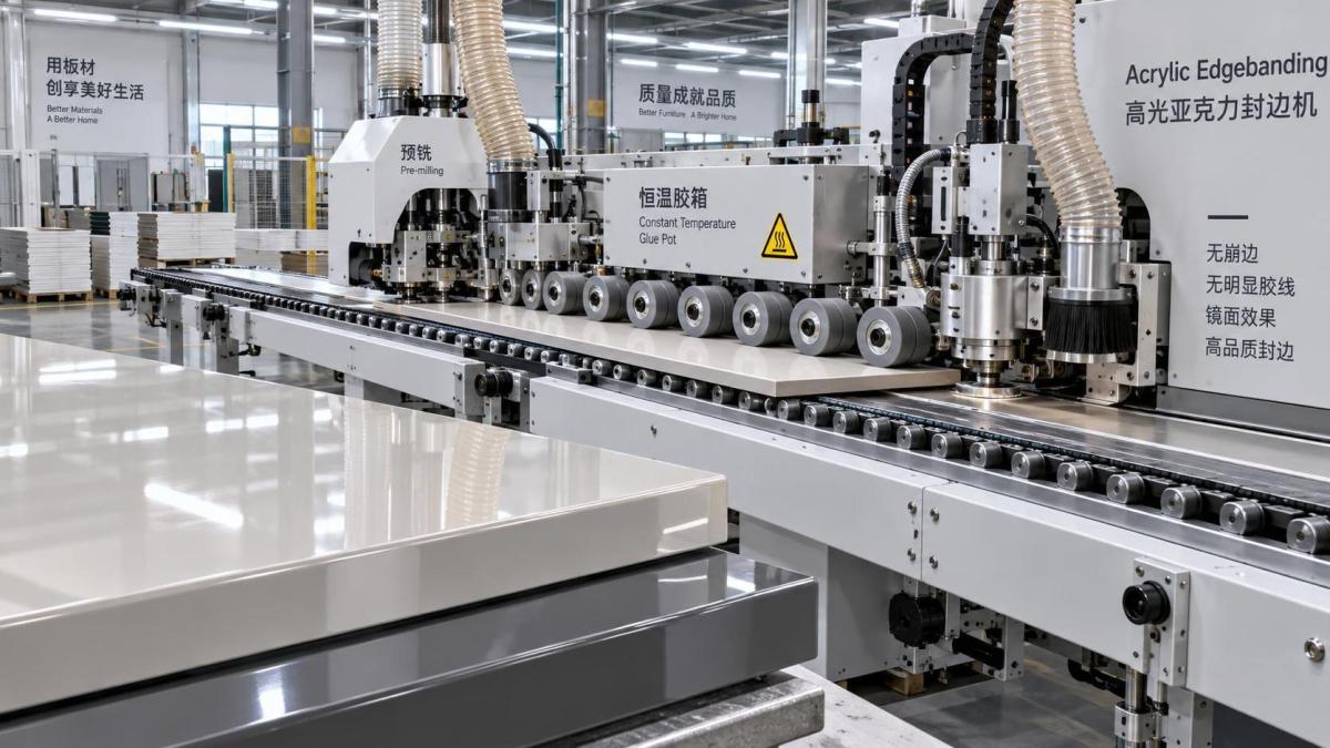
Inspection should include the beginning, middle, and end of long workpieces. A joint can look acceptable at the start yet show a glue-line change as the glue unit reaches thermal equilibrium, the panel feed load changes, or adhesive accumulates on a roller. This is one reason continuous production trials provide more useful selection evidence than a few short sample panels.
Trimming features that reduce acrylic chipping
Acrylic edge banding is vulnerable at the point where surplus material is cut away. Chipping is not solely a cutter problem. It results from the interaction of cutter sharpness, spindle runout, rotational speed, feed speed, edge-band support, workpiece stability, and the amount of overhang presented to the cutter.
End trimming deserves close attention because the leading and trailing corners have limited support. A unit with stable mechanical reference, appropriate cutter geometry, and dependable synchronization with panel movement reduces the risk of breakout. Pneumatic units can be effective, but repeatability of their motion and condition of their stop surfaces should be checked. Servo-controlled end trimming may offer advantages when frequent format changes, high production speed, or complex workpiece sequences require precise positioning; it does not eliminate the need for correct cutter selection.
For top and bottom trimming, separate rough and finish trimming stages are generally easier to tune for demanding acrylic work than a single cutter expected to remove all surplus in one pass. Rough trimming removes most of the overhang while leaving a controlled allowance. Fine trimming then produces the final flush surface with a lighter cut. This division reduces cutting load and helps avoid pulling or fracturing the edge at the board surface.
The quality of the reference mechanism is as important as the spindle. Copy shoes, sensing rollers, or contour-following elements should track the intended surface without scratching it, especially on protective-film-covered high-gloss panels. If the reference device follows an uneven protective film rather than the stable panel face, trim depth can fluctuate. Machines intended for acrylic work should provide enough adjustment range to accommodate band thickness and panel-face variation without forcing operators to improvise with spacer changes.
Spindle speed should not be assessed in isolation. A high nominal RPM with a poorly balanced cutter head or worn bearings can still leave chatter marks. Conversely, a stable spindle with a correctly specified cutter may produce better results at a lower line speed. The critical question is whether the machine maintains a clean cut at the intended production rate and across the full panel length, not whether it reaches an impressive maximum speed on a specification sheet.
Corner rounding, scraping, and buffing can improve an edge—or reveal a poor process
Corner rounding is frequently expected to remove all evidence of end trimming. It cannot reliably do so if the preceding cut has already chipped the acrylic or exposed an irregular glue seam. Its role is to create a controlled radius and remove sharp, fragile corners using a stable profiling path.
For acrylic edges, the rounding unit should have accurate workpiece tracking, rigid cutter support, and adjustment that is repeatable for different edge thicknesses. Corner geometry needs to match the band and finished design. An over-aggressive radius can cut into the decorative face or create a visibly flattened corner; an insufficient radius leaves a sharp edge that remains susceptible to damage during handling.
Scraping units are also often misunderstood. They can remove fine cutter marks and improve visual uniformity when correctly set, but excessive scraper pressure may create haze, white stress marks, or drag lines on acrylic. A machine with fine, repeatable scraper adjustment is preferable to one requiring broad manual movement. Separate glue scraping is valuable where squeeze-out must be removed without touching the glossy edge surface.
Buffing should be treated as a finishing stage, not a defect-repair station. Excess heat or contaminated buffing wheels can dull the surface or transfer residue. Where protective film is used, the production sequence must also establish whether the film remains during trimming and polishing or is removed at a controlled downstream point. That decision affects reference accuracy, cutter behavior, and final inspection criteria.
Automation matters when it preserves setup repeatability
Stored recipes, servo positioning, digital thickness readouts, and automated unit adjustment can reduce variation when several panel sizes, edge thicknesses, or colors are processed. Their value lies in repeatability. A recipe-driven machine should return the pressure beam, guide, glue gap, trimming depth, and profiling settings to verified positions with minimal manual correction.
However, automation should be matched to product mix and maintenance capability. A highly automated system with poorly documented reference settings, inaccessible adjustment points, or limited diagnostic information can create a different form of risk. During evaluation, it is useful to examine how the machine handles changeover, what settings remain manual, how operators verify actual positions, and whether alarm messages identify a process cause rather than merely stopping the line.
Equipment used elsewhere in a woodworking cell should not be confused with the functions required for edge finishing. For example, a Finger joint shaper MX3515A is designed for precision finger-joint cutting in solid wood, with its own spindle and tooling requirements. It may support upstream component preparation in a broader factory layout, but it does not replace the controlled gluing, pressure, trimming, and scraping sequence required for acrylic-edged panels.
What a meaningful acceptance trial should reveal
A credible machine comparison uses the actual board, acrylic band, adhesive, and finished edge geometry intended for production. Sample panels should include long parts, narrow parts, light and dark decors, and any thicknesses that will be processed routinely. Viewing the edge only from the operator side is insufficient; high-gloss components should be examined under oblique light, with protective film removed according to the normal production method.
Acceptance criteria should distinguish between separate defects: visible continuous glue line, intermittent glue starvation, adhesive squeeze-out, top or bottom chipping, end-corner breakout, trim chatter, mismatch at the joint, and surface haze. Combining all defects under a general “appearance issue” makes it harder to identify whether a configuration needs a glue adjustment, a different cutter, improved extraction, or better panel guidance.
The most dependable acrylic edge banding machine is not necessarily the one with the longest list of stations. It is the one whose panel reference, premilling, adhesive delivery, pressure zone, and finishing units remain mechanically stable and repeatable under the real combination of panel substrate, edge material, adhesive, and feed rate. Evaluating those interfaces directly is the practical route to fewer chipped edges, less visible glue, and a finishing process that can be maintained after installation rather than repeatedly corrected by hand.
Send Your Inquiry
We welcome your cooperation and we will develop with you.