


News & Exhibitions
Latest Factory Updates, Industry Trends & Global Exhibition Information
480V Woodworking Machine Setup: Checking Motors, Controls, and Protection
A woodworking machine can accept a 480V supply only when its motors, drives, control circuits, and protective devices are compatible with that supply. A “480V” label on the quotation is useful, but the electrical drawings and installed components must support it. One overlooked transformer connection or auxiliary motor can prevent an otherwise suitable machine from operating correctly.
Evaluating a woodworking machine 480V configuration therefore means tracing power from the incoming terminals through every connected load. Establish the supply voltage, phase, and frequency, then compare them with the machine’s documented configuration. Installation and commissioning should be performed by qualified electrical personnel using the manufacturer’s instructions and applicable electrical requirements.
Establish what “480V compatible” covers
Begin with the machine’s electrical nameplate, current schematic, component schedule, and installation instructions. These should describe the configuration being supplied, including any changes made for the destination market. A generic drawing covering several voltage options leaves too much room for assumptions.
Separate the review into three questions: Can each component operate on the available supply? Can the assembled machine carry and interrupt the expected current? Will its controls and safety functions behave correctly after installation?
The facility grounding arrangement deserves attention because some drives, filters, and surge protective devices have restrictions on the supply systems they can use. Also establish whether the machine requires a neutral. A three-phase supply does not automatically provide one, and a protective grounding conductor must never serve as a substitute.
Check every motor, including the small ones
The main saw or sanding motor usually receives the most attention. Feed motors, extraction fans supplied with the machine, hydraulic pumps, lubrication units, and cooling fans can be easier to miss. Create a motor schedule that records each motor’s rated voltage, frequency, current, connection, and starting method.
A 460V motor rating commonly accompanies a nominal 480V distribution system. The difference accounts for the relationship between distribution voltage and motor utilization voltage; it does not automatically indicate a mismatch. Suitability still depends on the motor’s permitted operating conditions, the voltage at its terminals, and the equipment manufacturer’s requirements.
A dual-voltage motor may be suitable for a higher-voltage connection, but only when its nameplate and terminal diagram explicitly provide that option. Changing the leads affects the motor winding connection. It does not convert the starter, control transformer, brake, or other components connected to the same machine.
Star and delta markings require particular care. Two voltages on a nameplate may describe different winding connections rather than two interchangeable supply choices. A star-delta starter must match both the supply and the motor’s intended running connection. Applying a familiar terminal arrangement without reading the motor diagram can expose windings to the wrong voltage.
Frequency is a separate compatibility check. A machine designed around a 50Hz supply should not be treated as ready for 60Hz simply because its voltage can be changed. Motor speed, cooling, and driven equipment behavior can change. For woodworking machinery, this may affect cutter speed, feed rate, pump output, or fan loading. Mechanical speed limits remain relevant even when the motor itself can operate.
Trace control power separately from motor power
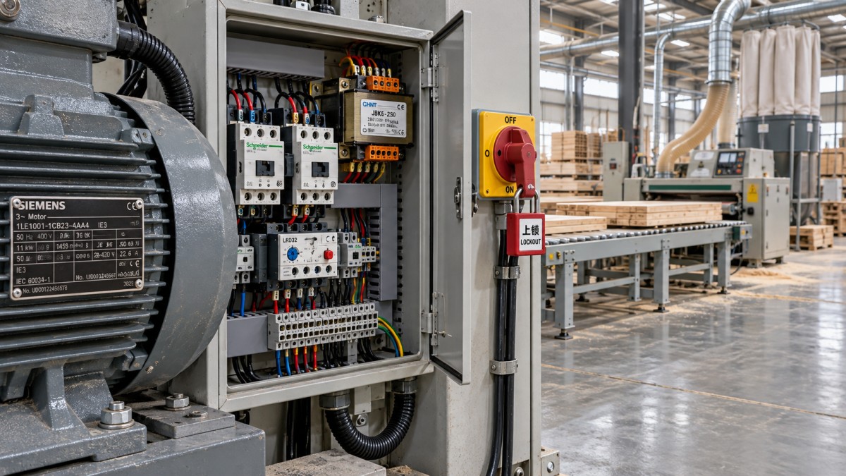
Control circuits often use voltages different from the incoming supply. A machine may distribute 480V to its motor starters while supplying contactor coils, sensors, a PLC, and an operator screen through transformers or DC power supplies. Each branch needs its own compatibility check.
For a control transformer, identify the primary rating, selected tap, secondary voltage, and capacity. A transformer with a suitable primary connection may support conversion, but the installed tap must match the actual supply. An incorrect connection can produce excessive or insufficient secondary voltage, damaging controls or causing contactors to drop out.
Review the loads connected to that transformer as well. Contactor pickup can impose a brief demand greater than the holding demand. A transformer that supports steady operation may still produce excessive voltage sag when several devices energize together.
Check contactor coils, brake rectifiers, cabinet fans, work lights, heaters, convenience outlets, and electronic power supplies individually. A wide-input DC power supply may accept several supply voltages, while an adjacent fan accepts only one. Component appearance provides little evidence of electrical compatibility.
Protective grounding, control-circuit referencing, and neutral distribution should be clearly distinguished on the schematic. Changing supply voltage is not a reason to improvise new connections between them.
Review drives and starting methods before changing connections
A variable frequency drive must have an input voltage rating suitable for the incoming supply. Its output current capability must also match the motor and application. A drive intended for a lower-voltage supply generally cannot be connected directly to 480V, and an ordinary drive should not be assumed to provide voltage boosting or electrical isolation.
Drive settings need to reflect the installed motor: rated voltage, current, frequency, speed, and permitted operating range. On a spindle or cutterhead, the maximum frequency setting must respect the mechanical limits of the complete assembly. Increasing frequency to restore an expected production speed can create a mechanical hazard if tooling, bearings, or the spindle are not approved for it.
Drive-controlled motors also require consideration of cable length, motor insulation suitability, and low-speed cooling. A feed motor that spends long periods at reduced speed may need a different assessment from a main motor that runs near its rated speed.
For contactor starters, soft starters, and star-delta arrangements, check power component ratings, coil supplies, interlocks, and timing against the revised configuration. Any change in starting behavior should also be considered alongside facility voltage drop and the machine’s restart sequence.
Separate overload protection from short-circuit protection
Motor overload protection addresses sustained excessive current and heating. Short-circuit protection addresses faults that can produce much higher currents. A machine needs both functions, although some devices combine them.
Overload selection and settings should follow the motor data, starter arrangement, manufacturer instructions, and applicable installation rules. A previous setting from a lower-voltage configuration cannot simply be retained. The relay’s measuring range must suit the motor current in the new connection.
The relay’s location matters too. In a star-delta circuit, an overload may measure line current or winding current depending on the design. Applying a setting intended for one arrangement to the other can produce incorrect protection. For a drive-fed motor, establish how the drive’s thermal protection is configured and whether additional protection is required.
A recurring trip should lead to investigation of the load and circuit. Blunt tooling, binding feed mechanisms, a jammed conveyor, phase loss, poor connections, and incorrect acceleration settings can all contribute. Raising the overload setting without identifying the cause can allow damaging heating to continue.
For fuses and circuit breakers, check voltage rating, interrupting capability, and the specified protective characteristics. Matching the current rating alone is insufficient. A device must be suitable for the system voltage and the fault current it may have to interrupt.
The machine’s short-circuit current rating must suit the available fault current at its connection point. A main breaker with a high interrupting rating does not automatically give the entire panel the same rating. Contactors, distribution blocks, drives, and other components can limit the assembly rating. Where a rating depends on a specified upstream protective device or tested combination, that condition belongs in the installation documentation.
Check the installation around the machine
Supply conductor sizing depends on the machine’s documented requirements, installation method, starting conditions, and applicable rules. Adding motor nameplate currents alone may not establish the correct feeder or protective device. The disconnect, terminals, and cable entries must also suit the installation.
Protective bonding should connect the cabinet, machine frame, motor frames, and other exposed conductive parts through the intended fault-current path. Painted joints, moving assemblies, and replacement components deserve inspection because mechanical attachment alone may not provide dependable electrical continuity.
Wood dust affects cabinet cooling and equipment selection. Locate and maintain enclosures so dust accumulation does not obstruct ventilation or compromise components. Areas subject to combustible-dust classification require equipment and installation methods appropriate to that classification; a standard electrical cabinet does not automatically meet those needs.
Commission through controlled checks
Before energization, qualified personnel should compare the installed wiring with the final schematic, inspect connections, verify protective bonding, and confirm device settings. Insulation testing must follow component instructions: applying a test voltage through connected drives, PLCs, or other electronics can damage them.
A useful commissioning sequence moves from supply verification to individual functions and then to representative production conditions:
- Verify the incoming supply. Measure the relevant voltages and confirm that the supply conditions match the approved configuration.
- Confirm control power. Check transformer secondary and DC supply outputs before releasing the machine for motion.
- Validate safety functions. Test emergency stops, guards, interlocks, and restart behavior using the manufacturer’s commissioning procedure.
- Check motor direction under controlled conditions. Follow the machine’s procedure with guards in place and personnel clear. Assess drive-fed motors separately from directly supplied motors.
- Observe operation under load. Check current, acceleration, feed behavior, vibration, and protective device performance during representative work.
Correct rotation alone does not establish that the machine is ready. A saw can rotate correctly while an extraction fan runs backward, and a conveyor can function while its overload setting remains unsuitable. Each function needs an acceptance check.
Make the approved configuration part of the order
The purchasing specification should identify the destination supply and require a matching electrical package. Ask for the final schematic, motor and drive schedule, control-power arrangement, protective device specifications, short-circuit rating, and commissioning requirements. Record responsibility for any site conversion before shipment.
When discussing a machine with Qingdao Zhongding Machinery Co., Ltd., use those documents to connect equipment selection with installation planning and later spare-parts support. Replacement contactors, transformers, fans, and drives should match the supplied electrical configuration, since a part for another voltage variant may look identical.
Release the machine for installation when the drawings, component ratings, protection requirements, and site supply agree. Retain the approved drawings and commissioning settings with the equipment so maintenance personnel can preserve that configuration throughout its service life.
Send Your Inquiry
We welcome your cooperation and we will develop with you.