


News & Exhibitions
Latest Factory Updates, Industry Trends & Global Exhibition Information
1300mm Calibration Sanding Machine Explained: How Dual-Reference Roller Systems Achieve ±0.03mm Flatness on MDF Edges
For technical evaluators assessing edge-finishing precision in MDF production, the 1300mm calibration sanding machine represents a benchmark in dimensional control—not because it sands faster or wider, but because it enforces flatness tolerance at the metrology level: ±0.03mm on board edges, consistently, across shifts and material batches. This is not a surface finish specification; it’s a thickness-control outcome achieved through mechanical synchronization, not post-process measurement correction. If your downstream CNC nesting or edge-banding lines are rejecting boards due to edge waviness, inconsistent lamination gaps, or fit-up failures in frame assembly, the root cause may lie upstream—in how edge geometry is stabilized *during* sanding, not just smoothed.
Dual-Reference Roller Systems: Why Two Points of Contact Change Everything
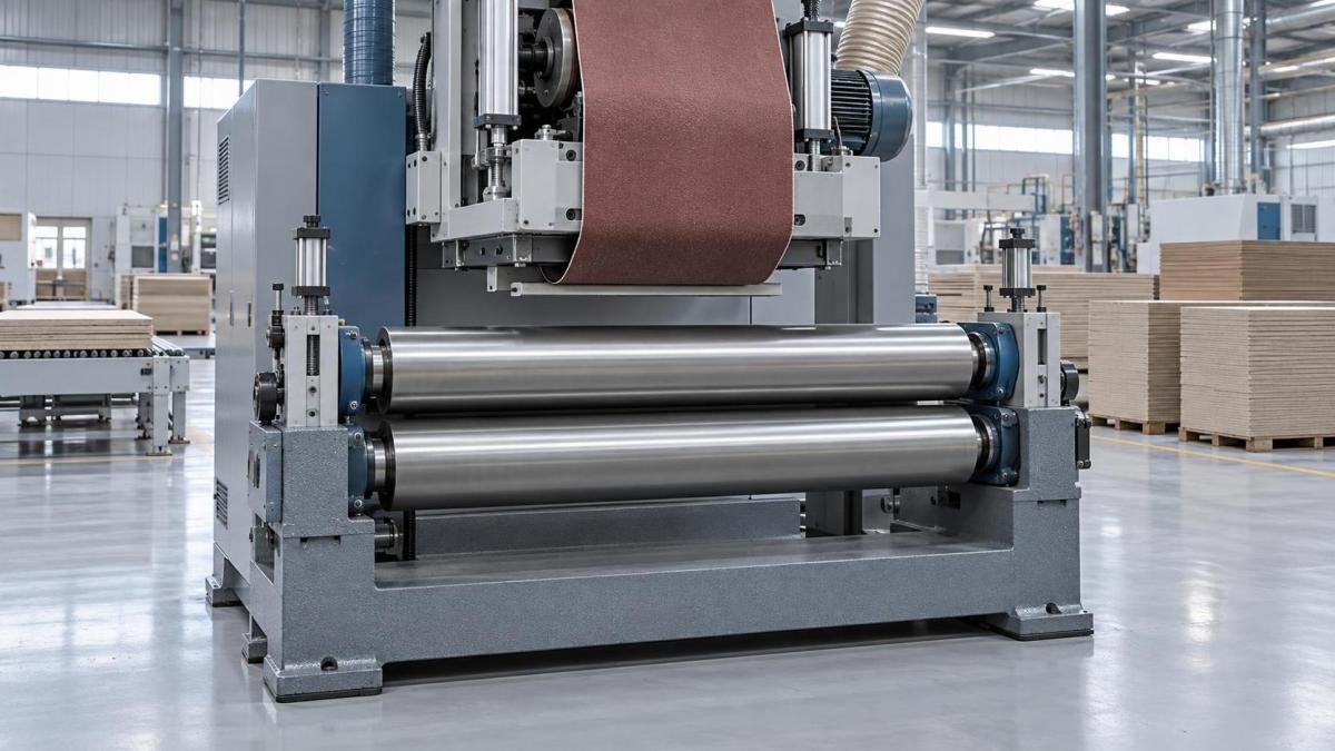
Standard edge sanders rely on a single reference roller or a floating shoe to guide the board. That approach works for cosmetic leveling but fails when dimensional repeatability matters. A single reference allows minor frame flex, belt drift, or roller wear to translate directly into edge profile deviation—especially on MDF, where density variation across the board width amplifies sensitivity to lateral force imbalance. The 1300mm calibration sanding machine eliminates that dependency by anchoring the workpiece between two independently driven, high-precision ground steel rollers—one upstream (infeed), one downstream (outfeed)—both mounted on rigid, thermally stable cast-iron supports.
These rollers do not merely support; they actively constrain. Each rotates at matched surface speed, synchronized to the conveyor belt within ±0.05% via servo-driven gearmotors and real-time encoder feedback. More critically, both rollers are vertically adjustable with micrometer-scale dials (0.01mm resolution) and locked using hydraulic clamping to prevent micro-shift under load. This dual-point constraint forces the board to conform to the geometric plane defined by the two rollers’ axes—effectively turning the entire machine into a dynamic, moving reference plane. Any local thickness deviation in the board induces measurable torque differential between the rollers, which the control system detects and uses to fine-tune feed rate or pressure distribution—not to “correct” the board, but to maintain consistent contact geometry.
How Rigid Frame Construction Enables Metrological Stability
The dual-roller concept only delivers ±0.03mm flatness if the frame holding those rollers remains dimensionally invariant during operation. Vibration, thermal expansion, or static deflection under 120+ kg/m load will degrade results regardless of roller precision. Qingdao Zhongding’s design addresses this with a monolithic base casting—650 mm deep, stress-relieved over 48 hours, and machined in a single setup on a horizontal boring mill. Critical bearing housings for both rollers are bored and honed in the same operation, ensuring coaxial alignment within 0.008 mm over 1300 mm span. The upper sanding head assembly is suspended from this base via three-point kinematic mounts, isolating it from frame resonance while maintaining vertical rigidity.
This isn’t about mass—it’s about modal stability. Finite element analysis confirms first-mode vibration frequencies above 180 Hz at full operating speed (24 m/min), well outside the excitation range of belt harmonics or motor torque ripple. As a result, roller runout remains below 0.005 mm even after 10,000 hours of continuous operation, and thermal drift across the 1300 mm width stays under 0.012 mm between ambient (15°C) and operational (32°C) conditions. That level of passive stability means the machine doesn’t require daily recalibration—just periodic verification with a certified master gauge block.
Real-Time Roller Feedback: Not Just Monitoring, But Constraint Enforcement
Each reference roller incorporates dual-axis load cells (radial and axial) sampling at 2 kHz. The control system doesn’t use this data to adjust sanding pressure alone. Instead, it monitors the *ratio* of load between infeed and outfeed rollers. In ideal operation, that ratio holds within ±1.8%—indicating uniform board engagement. Deviations beyond that threshold trigger automatic feed-speed reduction and re-evaluation of roller height settings before continuing. This is constraint enforcement, not process monitoring: if the board isn’t fully seated against both rollers, the machine slows down until geometry compliance is restored.
This differs fundamentally from systems that only monitor belt tension or motor current. Load imbalance reveals actual workpiece misalignment—often caused by warped board stock, uneven edge pre-machining, or accumulated dust in the roller grooves. Technicians can access live load ratio graphs on the HMI, overlayed with historical baselines from known-good runs. No interpretation needed: a sustained 3.2% imbalance over five consecutive boards points directly to infeed roller contamination, not abrasive wear or belt tracking.
Material-Specific Behavior: Why MDF Demands This Level of Control
MDF’s homogeneity is a double-edged sword. Unlike solid wood, it lacks grain direction to mask minor edge deviations—but unlike particleboard, its fine fiber structure allows sharp, clean edge definition *if* the substrate geometry is stable. However, MDF’s low internal bond strength makes it prone to localized compression under uneven pressure. A standard sander’s single-point reference may compress the leading edge while leaving the trailing edge uncontacted, creating a subtle taper no visual inspection catches—but one that causes 0.12 mm gap accumulation over a 2.4 m cabinet side panel.
The dual-roller system prevents this by distributing load evenly across the full edge length *before* abrasive contact begins. Pressure is applied only after the board is fully constrained—meaning the abrasive head engages a geometrically stable workpiece, not one being forced into shape. This also reduces heat buildup in the edge zone, minimizing resin migration and subsequent sanding belt glazing—a common cause of inconsistent removal rates across long production runs.
Operational Validation: What to Measure, Not Just Observe
Verifying ±0.03mm flatness requires more than checking a few random samples with a dial indicator. Use a granite surface plate and a 1300 mm straightedge with 0.01 mm feeler gauges. Place the sanded edge face-down on the plate, then slide the straightedge along the full length while inserting feelers at 100 mm intervals. Record maximum gap at each point. Repeat for three boards per shift, using the same orientation (e.g., all with factory-cut edge facing up). Consistent gaps ≤0.03 mm across all positions confirm system performance. Gaps exceeding tolerance only at the ends suggest infeed/outfeed roller height mismatch; mid-span deviations indicate belt tracking error or worn abrasive drum bearings.
No software compensation or “smart algorithms” substitute for mechanical constraint. When your edge-banding line reports adhesive starvation on the trailing 150 mm of panels, or your CNC router shows repeated tool-path deviation on nested parts, start here—not with the bander or router. The problem was fixed—or introduced—long before those machines saw the board.
Send Your Inquiry
We welcome your cooperation and we will develop with you.