


News & Exhibitions
Latest Factory Updates, Industry Trends & Global Exhibition Information
What determines edge quality in laminated board processing machinery?
Edge Quality Begins Before the Edge Banding Unit
Edge quality in laminated board processing is determined by the interaction of material structure, machine rigidity, tooling condition, cutting parameters, and dust control. A clean-looking edge is not simply the result of using a sharp cutter or running a high-end edge bander. It depends on whether the board is supported correctly, whether the cutting forces remain stable, and whether chips are removed before they are pressed back into the surface.
For quality control and safety managers, this matters because a poor edge is rarely only a cosmetic defect. Chipping can expose core material to moisture. Tear-out around holes can weaken hardware holding strength. Untrimmed or poorly bonded edge banding can create sharp contact points, reduce durability, and lead to rework at a late production stage. In high-volume furniture production, those defects also make it harder to distinguish an isolated operator issue from a machine condition that is becoming unsafe or unreliable.
The practical question is therefore not whether laminated board processing machinery can cut or edge-band a panel. It is whether the complete machine-and-process combination can produce a consistent edge across different panel batches, production speeds, and tool life stages.
The Board Surface and Core Set the Starting Limit
Laminated boards do not behave like solid wood. The decorative surface may be melamine paper, HPL, veneer, PVC film, painted film, or another overlay bonded to a particleboard, MDF, plywood, or composite core. Each layer responds differently to cutting pressure. A surface that is hard and brittle may chip at the exit point of a saw or router. A low-density particleboard core may crumble below an apparently intact laminate. A board with internal voids or uneven density can produce a clean edge in one area and an unacceptable edge several hundred millimeters later.
This is why edge defects should be evaluated as a material-process issue rather than assigned immediately to the machine. If chips appear consistently on one surface only, the likely causes differ from a defect that appears on both faces. Damage on the upper laminate can point to top-side support, scoring action, saw geometry, or insufficient pressure control. Damage on the lower face may indicate poor panel support, incorrect blade projection, or a mismatch between feed direction and cutter rotation.
Material variation also affects the settings that remain stable during a shift. A process tuned for a dense MDF panel may produce excess heat, fuzzing, or breakout when switched to a lower-density particleboard. Conversely, settings selected to avoid crushing a weak core may leave a harder laminated panel insufficiently supported during machining.
Incoming inspection does not need to become a full material laboratory to be useful. It should establish whether the panel thickness, flatness, surface condition, core density appearance, and laminate adhesion are consistent enough for the established process. When a new supplier, new decor, or new board construction is introduced, a short controlled trial is more informative than assuming that boards with the same nominal thickness will behave identically.
Cutting Stability Is More Important Than Peak Machine Speed
For saw cutting, CNC routing, drilling, and trimming, the machine must hold the tool and panel in a stable relationship. Spindle runout, worn bearings, poor clamping, damaged pressure rollers, and looseness in guides can each create a repeating defect pattern. The operator may respond by slowing the feed rate, but reduced speed only masks the underlying issue in some cases. It does not correct a spindle that is no longer running concentrically or a pressure system that allows a panel to vibrate.
Tooling condition is equally important, but “sharp” is not a sufficient inspection standard. Tool geometry must fit the material and process. Tooth count, hook angle, kerf, coating, cutter diameter, and insert profile affect chip formation and heat generation. A blade intended for solid timber may remove material aggressively enough to damage a brittle laminate. A cutter with the wrong geometry can create a polished but heat-affected edge that later interferes with adhesive wetting or edge-band adhesion.
Tool wear should be managed by output quality and process load, not only by elapsed operating time. A tool can appear intact while producing more force, heat, dust, and panel edge damage. Warning signs include a rising rate of minor chips, a rougher exposed core, increased motor load, more frequent need for parameter adjustment, or visible burnishing near cut lines. These changes should trigger inspection before defects reach assembly or packing.
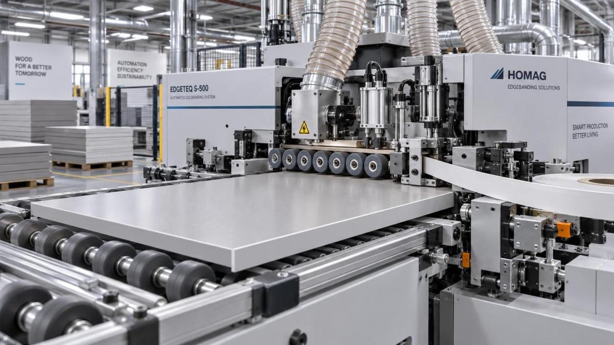
In Laminated Board Processing Machinery, panel restraint is often underestimated. A rigid machine frame cannot compensate for a board that lifts, twists, or shifts during processing. Hold-down devices, pressure beams, vacuum zones, conveyor belts, side guides, and reference fences must match the panel size and operation. Small components are particularly vulnerable because the available contact area is limited. A part that moves only slightly during trimming can produce inconsistent radii, uneven band overhang, or a sharp corner that will not be fully removed in the finishing station.
Feed Rate, Tool Speed, and Direction Must Work Together
Edge quality is strongly influenced by chip load: the amount of material removed by each cutting edge during each pass. Although production teams often adjust feed speed first, feed rate cannot be treated separately from spindle speed, tooth count, cutter diameter, and material type. Excessive chip load can pull fragments from the laminate or crush the core. Too little chip load can create rubbing instead of controlled cutting, raising temperature and leaving a glazed or discolored edge.
The correct setting is therefore a stable operating window, not a single universal number. Within that window, the cut is clean, the machine load is predictable, and the tool does not overheat. Outside it, defects can change quickly. A feed increase that looks harmless on a plain melamine board may produce edge breakout when a textured surface or thinner laminate is processed.
Cutting direction also matters. Climb cutting and conventional cutting can leave visibly different edges, particularly when routing laminated surfaces. One direction may reduce surface breakout but increase the tendency for the workpiece to move if clamping is inadequate. The selected strategy has to account for both finish quality and safe workpiece control. Changing rotation direction or process sequence without checking restraint conditions can create a safety issue as well as a quality issue.
For panel saws, scoring is often the deciding factor for a chip-free lower laminate surface. The scoring blade must be aligned with the main blade and set to the appropriate width and height for the actual kerf. If the scoring path is narrower than the main cut, the main blade can still tear the surface. If it is too wide, a visible groove may remain outside the intended cut line. Alignment should be verified after blade changes, maintenance work, or any recurring defect concentrated on one face of the panel.
Edge Banding Quality Depends on the Cut Edge It Receives
Edge banding is sometimes treated as a separate finishing operation, yet its result is directly linked to upstream cutting quality. Adhesive cannot reliably compensate for a crushed, dusty, overheated, or uneven substrate. A rough particleboard edge may absorb adhesive unevenly. A burnished MDF edge may reduce wetting. Loose fibers and chips can create channels that later appear as gaps, weak sections, or visible adhesive lines.
The edge banding unit must also maintain stable panel guidance. Glue application, tape placement, pressure roller force, trimming, scraping, and buffing are sequential operations. A small positioning error at entry can remain visible through the final panel. If the board is not referenced consistently, one edge may receive uneven band overhang, leading to excessive trimming on one side and inadequate cleanup on the other.
Quality teams should inspect the finished edge as a system rather than limit checks to whether the tape remains attached. Relevant observations include:
- surface chips or fractures next to the banded edge;
- open glue lines, dry spots, or adhesive squeeze-out;
- gaps at the leading and trailing ends;
- banding that sits proud, recessed, or unevenly trimmed;
- sharp corners, knife marks, or exposed core material;
- variation between the first, middle, and last panels in a production run.
A localized end defect may be associated with entry pressure, end trimming, or part handling. A continuous defect along the full edge is more likely to involve cutting condition, glue application, pressure rollers, or board condition. This distinction helps prevent broad machine adjustments when the cause is confined to one station.
Dust Extraction Has a Direct Effect on Quality and Safety
Dust extraction is often evaluated mainly as an environmental and housekeeping requirement. In laminated board machining, it is also a process-control function. Fine dust left in a saw kerf or on a routed edge can be compacted into the surface, interfere with adhesive contact, obscure a developing defect, and increase heat around the cutter. Larger chips can be dragged against a finished laminate and leave scratches that may only become obvious under inspection lighting.
Insufficient extraction can also make diagnosis unreliable. A rough edge covered with dust may appear acceptable at the machine, while the true tear-out becomes visible only after wiping or downstream assembly. Inspection procedures should therefore define how an edge is cleaned before visual acceptance. Checking panels while dust is still present invites inconsistent judgments between shifts.
From a safety perspective, extraction performance should not be inferred only from whether ducts appear connected. Blockages, worn hoses, poorly positioned hoods, damaged seals, and overloaded collection systems can reduce capture at the cutting zone while leaving the machine apparently operational. The result can be higher airborne dust exposure, accumulation around moving components, and reduced visibility for operators. When edge quality and dust conditions deteriorate together, treating them as separate maintenance issues can delay the actual correction.
How to Turn Edge Defects into Useful Process Signals
Visual standards work best when they describe defect location and severity in clear terms. “Poor edge” is too broad to support corrective action. A practical inspection record distinguishes between upper-surface chips, lower-surface chips, core breakout, fuzzy edges, burns, banding gaps, sharp edges, and dimensional deviation. It should also identify the machine, operation, tool set, board type, panel orientation, and time in the run.
The purpose of this type of record is not to assign blame to an operator or department. It is to identify whether a defect repeats by panel orientation, tool position, material batch, time interval, or machine station. Repetition is valuable evidence. A defect occurring at regular intervals may indicate tool damage or a rotating component issue. A defect that begins after a tool change may point to setup, alignment, or tool specification. A defect limited to one board batch should prompt material segregation and a review of the processing window before the machine is extensively adjusted.
A Controlled Response Is Better Than Repeated Adjustment
When edge quality falls, production teams often change several settings at once: lower feed speed, raise spindle speed, increase pressure, alter adhesive temperature, and replace a tool. That may restore appearance temporarily, but it removes the ability to identify the cause. It can also introduce new risks, such as excess heat, panel damage from overpressure, or reduced throughput without a measurable quality gain.
A more reliable response starts with defining the defect and isolating the affected operation. Confirm the board type and orientation, inspect the tool and restraint system, verify dust extraction at the cutting point, and compare the result with a controlled sample. Change one relevant variable at a time where production conditions allow. The final setting should be documented with the board construction and tool configuration it was validated against.
Clean edges are produced by a controlled process, not by any single machine specification. A rigid spindle, suitable tool, stable feed, effective hold-down, aligned scoring system, clean cut surface, and functioning extraction system reinforce one another. For quality and safety managers, the strongest control point is a process that makes deterioration visible early, before minor edge damage becomes a recurring product defect or a wider operational problem.
Send Your Inquiry
We welcome your cooperation and we will develop with you.