


News & Exhibitions
Latest Factory Updates, Industry Trends & Global Exhibition Information
Integrating an Automatic Panel Saw Into a Cabinet Production Line
An automatic panel saw can improve cabinet production only when its cutting cycle fits the flow of sheets into the machine and parts out of it. A faster saw will not resolve a bottleneck at labeling, sorting, edge banding, or CNC machining; it can instead create larger queues and make part identification harder.
The integration decision therefore starts with the production mix and the intended path of each panel, not the saw’s maximum cutting speed. Layout, software data, dust extraction, safety, installation downtime, and acceptance criteria need to be coordinated as parts of the same project.
Define the production flow before fixing the machine specification
Cabinet lines operate under different constraints. A line producing repeated carcass components from a limited range of boards can favor larger batches and stable cutting patterns. A made-to-order line may process many board colors, thicknesses, and cabinet configurations in short batches. In that environment, the ability to keep parts identified and grouped for later operations can matter as much as raw cutting output.
Map a representative production sequence from sheet storage to the next processing station. Include receiving or staging boards, loading, cutting, labeling, unloading, sorting, edge banding, drilling or routing, and temporary storage. Identify where sheets change direction, where operators handle individual parts, and where jobs wait for equipment or instructions.
Use actual production records where available: sheet sizes and thicknesses, material types, typical part dimensions, daily or shift demand, batch sizes, and the proportion of mixed orders. A representative sample should include difficult jobs, not only the easiest high-volume pattern. Small parts, decorative surfaces, grain direction, and parts requiring different downstream operations can all change handling time and cutting plans.
For an existing line, establish the current constraint before assigning an output target to the saw. If edge banding already operates near its practical capacity, increasing cutting output without additional sorting space or downstream capacity may only increase work in process. Conversely, if cutting is delaying assembly, the project should account for the people and equipment needed to remove and route parts at the new rate.
Size capacity around complete jobs, not the fastest cut
A machine’s stated cutting speed or theoretical cycle rate is not the same as usable production capacity. The working cycle also includes loading, positioning, cutting-pattern changes, unloading, labeling, offcut handling, and interruptions. The balance depends on the saw configuration and the production mix.
Capacity planning should express demand in a unit that corresponds to the decision being made. Sheets per shift can help estimate loading demand, but parts per shift and the mix of part sizes are more useful for understanding downstream handling. A complex sheet yielding many small components can occupy the unloading and labeling area longer than a sheet producing a few large panels, even when both require one sheet to be loaded.
Build a capacity estimate using representative cutting patterns and the intended staffing arrangement. Record the assumed shift length, productive time, loading method, number of operators, material presentation, and treatment of offcuts. Where stacked cutting is proposed, check that board type, stack height, surface protection, required accuracy, and the supplier’s machine limits support the plan. A capacity calculation based on a stack that cannot be used for the actual mix will overstate output.
Allow for planned maintenance and normal production interruptions separately from the cutting cycle. Then compare the achievable output with the capacity of loading, labeling, sorting, and the next constrained process. The purpose is not to force every station to have identical capacity, but to make the resulting buffers and staffing needs explicit.
Design the layout around sheet entry and part exit
The saw footprint is only part of the space requirement. Full-size sheets need a practical route from storage to the loading position, including turning and lifting clearance. Finished parts need room for safe removal, identification, inspection, and placement on carts, pallets, or conveyors. Access for blade changes, cleaning, electrical cabinets, and maintenance must remain available after surrounding equipment is installed.
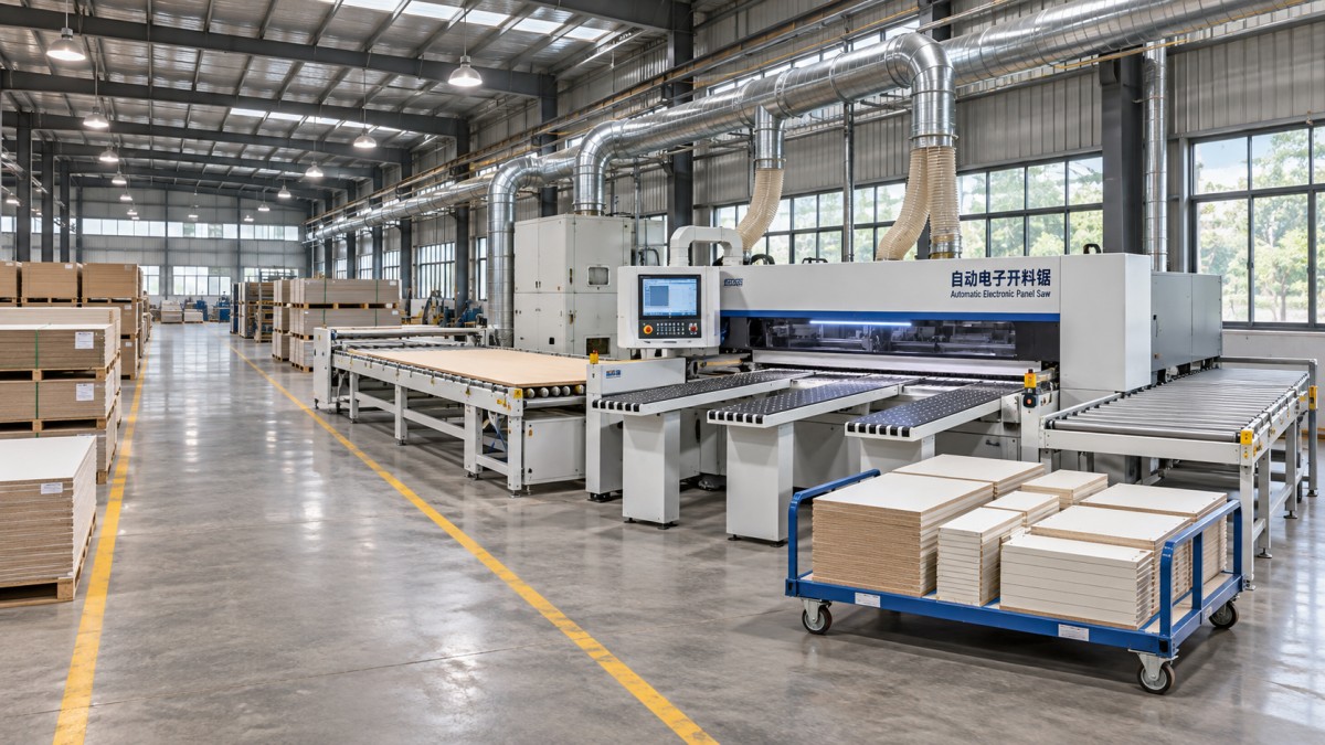
Draw the layout using the largest sheet size and the longest parts to be handled, rather than relying only on the machine outline. Show forklift and pedestrian routes, operator positions, maintenance zones, dust-extraction connections, and the locations of emergency stops and isolators. Check whether a delivery or removal route crosses the saw’s operating area or blocks access to adjacent machines.
The loading method should reflect both sheet volume and material mix. Manual loading can be suitable where throughput is moderate and board changes are frequent, provided sheet weight and handling risks are addressed. Lifting aids or automated loading can reduce manual handling, but they require clear material presentation, sufficient space, and a defined approach to different sheet sizes, warped boards, and surface protection. The expected benefit should be evaluated against the complete flow, including how quickly cut parts can be cleared.
At the outfeed, decide whether parts will be sorted by cabinet, customer order, material, edge-banding requirement, or next machine. Each rule has different space and handling consequences. Sorting immediately by order may reduce later searching, but it can require more destinations beside the saw. Sorting by next operation may simplify transfer while creating a later need to regroup components. The chosen method should be tested against a representative mix of orders before floor space and carts are finalized.
Connect cutting data to physical part control
Integration with production software is not simply a question of whether two systems can exchange a file. The data must remain usable from the cutting plan through to the finished component. A typical chain begins with cabinet design or an order system, moves through a cut-list or optimization application, and ends with machine instructions and part labels. Each handoff needs a defined owner and a way to detect errors.
Confirm which system creates the cutting patterns, what file formats and fields are supported, and how programs are transferred and approved. Material codes, finished dimensions, board thickness, grain direction, part identifiers, and edge-banding instructions need consistent definitions. Clarify whether dimensions in each system refer to the cut blank or the finished part after later processing; an unnoticed difference can produce parts that cannot be corrected downstream.
Label timing is an operational decision as well as a software feature. A label applied to the correct face at the right time can carry the part identity to edge banding and machining. A label that obscures a reference surface, damages a decorative finish, falls off, or is applied after parts are mixed can undermine traceability. Where labels carry barcodes, verify that downstream scanners and software can interpret the same identifier.
Agree on an exception procedure before production starts. It should cover a damaged part, an incorrect label, a missing board, a partial sheet, and a remake. The operator needs to know whether the original program can be reused, how the replacement is identified, and how the production system records the change. Without that procedure, a software-connected saw can still produce physically untraceable parts.
Resolve utility and safety interfaces before delivery
Site readiness should be checked against the selected equipment’s installation documents, not a generic utility allowance. Electrical supply, protection, grounding, compressed air where required, and network connections must match the machine and local installation requirements. Confirm connection points and responsibility for work outside the machine boundary, including isolators, cabling, piping, and commissioning support.
Dust extraction requires particular coordination. The extraction system must serve the saw’s specified connection points and operating requirements while accounting for the rest of the plant, duct routing, and the effect of other machines operating simultaneously. A connection that fits physically is not proof that capture performance is adequate. Define who will assess the extraction system and how performance will be checked under operating conditions.
Machine guarding and protective devices must be considered together with the surrounding material flow. A layout that leaves room for a conveyor but requires personnel to reach into a hazardous zone is not an acceptable integration. Changes to guarding, controls, or interlocks should be managed with the relevant suppliers and assessed against applicable local safety requirements. Access for clearing jams and maintenance also needs a controlled isolation procedure; an emergency stop is not a substitute for energy isolation.
Other site checks include floor condition and load capacity, anchoring requirements, ceiling and lifting clearances, delivery access, and environmental conditions specified for the equipment. Resolve discrepancies while drawings can still be changed, rather than after the machine has arrived.
Schedule installation around production dependencies
A practical implementation schedule identifies more than the delivery and installation dates. It links prerequisites to the parties responsible for them: final layout approval, foundation or floor work where required, utility completion, extraction installation, software configuration, equipment delivery, mechanical and electrical installation, safety checks, training, and production trials.
For a running factory, define the cutover point and the consequences of delay. Existing equipment may need to remain available until the new saw has demonstrated that it can process representative work. If space constraints require the old saw to be removed first, the schedule should include a contingency for cutting capacity, such as planned inventory or an alternative processing route. That contingency must reflect material availability and the shelf space needed for partially completed jobs.
Software and labeling preparations can often progress before the machine arrives, provided the interface specifications are settled. Clean material codes, agree naming rules, prepare sample jobs, and verify label content in advance. This reduces the risk that mechanical installation is complete while production data remains unusable.
Maintain a single interface register for decisions that cross supplier and site boundaries. It should record the required information, responsible party, due date, current status, and impact of an unresolved item. Typical entries include the exact extraction connection, program file format, conveyor handoff height, network access, and responsibility for removing installation waste. These details can affect the critical path even when the saw itself is delivered on time.
Accept the integrated process, not just the machine
Acceptance criteria should be agreed before purchase and should distinguish a machine test from a production-line test. A factory test, where included, can check machine functions and sample cutting before shipment. Site acceptance must also address the installed utilities, actual material flow, software transfer, labeling, safety functions, and operator readiness. Passing one test does not automatically establish the other.
Select test jobs that represent the intended workload: different board thicknesses and finishes, large and small components, grain-sensitive parts, and at least one mixed-order pattern if that is part of normal production. Agree on the measuring method, sample size, dimensional tolerances, and acceptable edge quality for those jobs. The limits should be compatible with both the machine specification and downstream process needs.
Run the test with the planned loading and unloading arrangement. Record elapsed time and interruptions, but also check whether every part can be identified, sorted, and transferred without an improvised workaround. If the saw meets its cutting target only when extra staff temporarily clear the outfeed, the result should not be treated as proof that the planned staffing model will sustain that output.
Separate defects that prevent safe operation or production from minor outstanding items, and assign a resolution date and owner to each. Training should cover program selection, material and label checks, routine inspection, blade-change procedures, fault reporting, and safe recovery from a stoppage. Maintenance personnel also need access to documentation, spare-parts information, and the procedures required for the installed configuration.
After handover, compare production results with the assumptions used to justify the installation. If output is below plan, examine waiting time at loading and outfeed, sorting delays, program availability, and downstream congestion before attributing the gap to cutting speed. The useful measure of integration is whether correctly identified parts reach the next operation at the required rate and quality, with a workflow the factory can maintain.
Send Your Inquiry
We welcome your cooperation and we will develop with you.