


News & Exhibitions
Latest Factory Updates, Industry Trends & Global Exhibition Information
How cabinet process consultation helps prevent hole alignment errors
How cabinet process consultation helps prevent hole alignment errors
Misaligned cabinet holes can turn a routine assembly into a quality failure. Dowels will not seat, cam connectors pull panels unevenly, and hardware needs adjustment that should never have been necessary. Rework adds another problem: operators may be tempted to enlarge holes, force joints together, or drill unsupported panels by hand.
Preventing these defects starts before drilling. Effective cabinet manufacturing process consultation examines how design dimensions become machine coordinates, how panels locate against stops, and how inspection confirms that mating parts actually fit. The useful outcome is not simply a corrected drilling program. It is a controlled process that keeps the same error from returning on the next shift or product revision.
Start with the failed joint, not the machine settings
When a cabinet side and bottom panel will not assemble, adjusting the drilling offset may look like the quickest solution. It is also an easy way to conceal the original cause. The hole could be correctly positioned relative to the programmed origin while that origin is wrong for the assembly.
A process review should begin with the mating components, their approved drawings, the hardware specification, and the production records. Identify which surfaces should meet, which edges establish the dimensions, and whether the fault affects every component or appears intermittently. Keep rejected parts available; replacing them before investigation removes useful evidence.
The defect pattern helps narrow the investigation:
- A consistent displacement across a complete hole group suggests a reference, offset, or program issue.
- An error that increases along a row warrants checks of panel squareness, positioning angle, and machine geometry.
- Intermittent displacement points toward variable seating, debris, clamping, or material movement.
- A problem limited to mirrored components makes orientation and program selection immediate suspects.
These are investigation routes, not diagnoses. One symptom can have several causes, so measurements should confirm the explanation before production settings change.
Agree on the reference edge before discussing accuracy
One of the most consequential consultation questions sounds almost too simple: “Which edge are we measuring from?” Design, machining, and inspection may each have a reasonable answer, yet those answers may not match.
Consider a side panel drilled before edge banding. The program locates a hardware hole from the substrate edge, while inspection checks its position from the finished front edge. Unless the process accounts for the edging and any subsequent trimming, a good machining result can appear incorrect—or a genuinely incorrect finished dimension can pass an upstream check.
Consultation should establish a shared datum scheme: the reference face, reference edge, loading orientation, and stage at which each dimension applies. Where practical, show these directly on setup drawings and work instructions. “Front” alone is not enough when left-hand and right-hand parts arrive at the machine in different orientations.
Panel thickness also belongs in this discussion. An edge hole intended to meet a face-drilled connector depends on the relevant hardware geometry and actual panel dimensions. A nominal thickness in the design library does not prove that the delivered board, tool setup, and connector requirement are compatible.
Trace one component from drawing to drilling
A productive review follows one representative component through the entire data path. Compare the approved drawing, CAD/CAM output, post-processed machine file, displayed setup, and physical panel. Looking only at the design model misses mistakes introduced later.
Pay particular attention to face changes and mirrored parts. A hole pattern that looks correct on screen can be machined on the wrong face if the software convention and loading instruction disagree. Rotation, origin selection, and machining-side definitions must remain consistent through the handoff.
Hardware libraries deserve the same scrutiny. Changing a connector without reviewing its hole positions, diameter, and depth requirements can leave an apparently familiar cabinet using an incompatible drilling pattern. The approved hardware documentation should govern those features, rather than an old program that operators know “usually works.”
The control here is revision discipline. Released drawings, machining files, labels, and setup sheets need to identify the same revision. A consultation should define who authorizes changes and what triggers a new first-piece check. Unrecorded controller edits may rescue one batch while creating a mismatch when the original file is downloaded again.
Separate machine capability from panel-positioning problems
A precise woodworking machine cannot compensate for a panel that does not sit against its intended references. Before requesting calibration, check the contact surfaces, locating stops, support arrangement, and clamping sequence under the machine manufacturer’s safe procedures.
Chips against a stop can shift a component. A bowed panel may sit differently before and after clamping. Narrow pieces may lack adequate support, while a pressure device can move a panel if it engages before location is secure. These conditions call for different corrections; increasing clamping force indiscriminately can distort the workpiece rather than solve the problem.
On CNC nesting equipment, workholding deserves attention, especially for small parts or operations performed after surrounding material has been removed. On point-to-point machines and drilling lines, review stops, pressure devices, transfers, and any repositioning between operations. The relevant checks depend on the actual machine configuration.
Then examine tooling and mechanical condition. Incorrect tool length settings affect depth; worn or unsuitable drills can affect hole quality; spindle or drill-head condition can influence the finished result. Do not describe every assembly difficulty as a coordinate error. An undersized, damaged, or insufficiently deep hole may resist assembly even when its center is correctly located.
Where possible, compare repeated machining on a suitable reference workpiece with results from production panels. This helps distinguish machine repeatability from variation introduced by the material or loading method, without assuming either is at fault.
Inspect the relationship between holes, not just individual dimensions
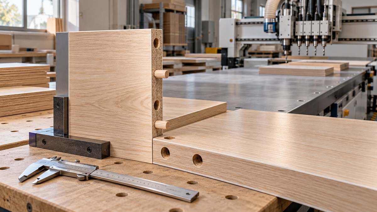
Two panels can pass separate checks and still fail to assemble. This happens when the inspection plan measures convenient dimensions rather than the relationships that control the joint. For a dowelled connection, those relationships include the mating hole locations, relevant depths, and the way the panel edges meet.
Acceptance limits should come from the cabinet design, hardware requirements, and functional needs. There is no universal hole-position tolerance suitable for every connector and board material. Clearance that is acceptable for one fitting may leave another loose or impossible to assemble.
Cabinet manufacturing process consultation should turn those requirements into practical inspection points:
- Check the first mating set after a setup, relevant tooling change, or program revision.
- Measure critical features from the same datums used in the approved process.
- Use suitable gauges or measurement methods; measuring a rough hole edge with a ruler may not resolve the required positional difference.
- Include a controlled assembly check where dimensional inspection alone does not establish fit.
- Define containment for affected work when a check fails, rather than continuing until assembly reports more rejects.
A fit check should not become a force test. If the joint needs unusual pressure, stop and investigate. Forcing it together can damage the panel or connector and hide a defect that becomes visible only after handling or installation.
Make the correction safer than the workaround
Hole misalignment creates pressure to improvise. Someone may suggest opening a hole with a handheld drill, moving a panel while it remains clamped, or reaching into a machine to clear material. A useful consultation considers these foreseeable responses, not just the original machining fault.
Rework needs a defined approval route. Confirm whether the revised hole will preserve connector engagement, joint strength, and the required finished condition. If those requirements cannot be demonstrated, replacing the component may be more appropriate than repair.
Any approved rework should use suitable support, workholding, guarding, and dust control. Inspection, maintenance, and intervention inside hazardous machine areas must follow applicable energy-isolation procedures and manufacturer instructions. Bypassing an interlock to diagnose an alignment issue is not an acceptable shortcut.
Record the reason for rework as specifically as possible. “Hole wrong” is difficult to act on; “front locating stop contaminated” or “mirrored file loaded for opposite-hand panel” gives the next investigation a useful starting point.
Leave the consultation with controls that survive the next shift
The final deliverables should be usable on the shop floor: an agreed datum drawing, controlled machining files, a clear loading instruction, critical inspection criteria, and a response plan for failed checks. Assign ownership for unresolved actions. A recommendation to “improve operator training” is insufficient unless it identifies the task and how competence will be verified.
Machine-supplier input can help connect these controls to the equipment. Qingdao Zhongding Machinery Co., Ltd., a woodworking machinery manufacturer and exporter with more than 20 years of industry experience, provides technical support, spare parts supply, and after-sales service alongside its machinery. For an alignment investigation, that support is most useful when supplied with drawings, machine details, tooling information, program revisions, and measured defect patterns—not just a photograph of an unfinished joint.
Before releasing the next batch, verify the correction on mating components under normal production conditions. A successful test panel is encouraging; repeatable fit after ordinary loading, machining, and handling is the stronger basis for release.
Send Your Inquiry
We welcome your cooperation and we will develop with you.