


News & Exhibitions
Latest Factory Updates, Industry Trends & Global Exhibition Information
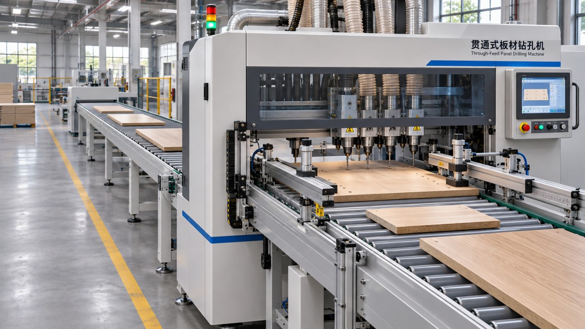
Can a through-feed drilling machine handle mixed panel sizes?
A through feed drilling machine for panel furniture can process mixed panel sizes when its transport, positioning, drilling heads and control software accommodate the complete production mix. The decisive distinction is whether different panels can run consecutively from separate programs, or whether each size requires manual adjustment, a different fixture or a change in drilling setup.
For selection, compare the actual combination of panel dimensions, hole patterns and production sequence with the machine’s permitted operating conditions. A panel that fits within the advertised length and width range may still be unsuitable if it cannot be clamped securely, if its holes fall outside the drilling head’s reach, or if the next panel requires a manual reset.
Start with the size envelope, not the largest panel
A machine specification normally identifies minimum and maximum panel length, width and thickness. All three limits matter, but they do not necessarily describe a rectangular range in which every combination is acceptable. A very short, wide panel may behave differently from a long, narrow one, even when each dimension falls within its individual limit.
Short panels present a particular transport challenge. There must be sufficient contact with feed rollers, belts or other conveying elements as the panel enters, stops for drilling and exits. If the panel loses positive control between transport zones, its position can shift before the drilling cycle. Long panels create a different concern: unsupported overhang can cause sagging or skew, especially when the material is thin or flexible.
Thickness influences more than whether a panel fits under the pressure system. Clamping travel, pressure settings and tool projection must suit both extremes of the production mix. A thin panel that lifts during drilling can produce inconsistent hole depth or damage around the exit face; a thick panel may limit the available drill reach or interfere with a head or clamp.
Ask for a working-range diagram or written clarification when minimum length varies with width, drilling face, feed direction or the number of active heads. The useful range is the range available for the intended operation, not simply the range through which a blank panel can travel.
Positioning determines whether sizes can be mixed reliably
Through-feed systems establish a panel reference using some combination of side guides, stops, sensors, clamps and motion feedback. The control program then locates holes relative to that reference. For mixed dimensions, confirm which edge and end define the datum and whether that datum remains consistent as panel sizes and orientations change.
A panel registered against the wrong edge can produce a pattern that looks correct in isolation but does not assemble correctly with its mating part. This is especially easy to miss on nearly symmetrical components. Clearly define the reference face, reference edge and leading end in both the part data and the physical loading convention.
Machine positioning accuracy also needs a practical interpretation. Repeatability describes how closely repeated cycles return to the same position; it does not by itself establish that holes are correctly located relative to the finished panel edge. Sawing variation, edge chipping, panel bow and inconsistent registration can all affect the assembled result even when the machine repeats its motion reliably.
For long or narrow parts, pay attention to skew. A small angular deviation at the guide becomes a larger positional error farther along the panel. Clamping must hold the reference position through drilling without pushing the panel away from its datum. Where both faces or multiple edges are machined, establish how the machine maintains or re-establishes the reference between operations.
Hole patterns can impose tighter limits than panel size
The drilling envelope is often different from the panel envelope. A machine may accept a large panel while a particular spindle cannot reach every required hole, or it may accept a small panel only when clamps occupy positions that conflict with the pattern. Compare the complete hole coordinates with the travel and accessible area of each relevant head.
Distinguish vertical face drilling from horizontal edge drilling. Face holes for hinges or connectors, edge holes for dowels and holes on opposing edges can require different heads, panel positions or passes. A stated capability to drill several faces does not establish that every combination is available in one pass. Ask how the panel is turned or re-referenced when a required face is inaccessible.
Drill-bank configuration matters as well. Fixed spindle spacing is efficient when holes match the available spacing, but an irregular pattern may require repositioning, selective spindle activation or an additional tool. Confirm the available drill diameters, depth control, tool-change arrangements and whether the same program can call the needed tools without manual intervention.
Clamps and pressure beams deserve attention during pattern review. A hole near a panel end may be technically within the head’s travel but inaccessible while the panel is held in the required position. The smallest parts and holes close to edges are useful cases for exposing such restrictions.
Automatic changeover requires complete part data
Consecutive mixed-size processing requires the control to associate each physical panel with the correct machining program. Depending on the installation, that association may come from a scheduled sequence, barcode identification or another production-data interface. Confirm whether dimensions and hole coordinates are read from each part record, selected from stored programs or entered manually.
The control also needs a way to react to incorrect or missing information. A useful acceptance test includes a panel presented in the wrong orientation, an unreadable identifier and a mismatch between the scheduled part and the panel at the infeed. Establish whether the machine stops, rejects the part or requires confirmation, and how the sequence is recovered without assigning the next program to the wrong panel.
Panel size change does not automatically imply a drilling-pattern change, and the reverse is also true. Two panels of identical dimensions can require different hole locations, depths or reference faces. Conversely, a family of different lengths may share a parameterized pattern. The programming method should reflect the actual part data rather than rely on size alone as an identifier.
Automatic adjustment should be described by function. Side guides, clamps, drilling heads and feed settings may have different adjustment methods. A machine with automatic program selection can still require a manual guide adjustment; automatic positioning of one axis does not prove that all relevant hardware changes over without intervention.
Separate machine capability from line capability
A drilling unit can accept mixed sizes while the connected line cannot deliver them in the required order or orientation. Infeed rollers, transfer tables, conveyors and outfeed supports each have their own minimum and maximum dimensions. Small parts can encounter gaps between sections; large parts can obstruct transfers or require additional support.
Spacing between consecutive panels also affects throughput. The machine may need a clear interval to identify a part, close clamps, complete drilling and release it before the next part enters. A sequence containing frequent changes in size or hole pattern can therefore run differently from a continuous batch of identical panels. Compare output using the intended product mix, including transfers and any turning or reorientation.
Material and surface condition influence feeding. Laminated particleboard, MDF and other panel products do not necessarily behave alike under the same pressure and feed conditions. Dust, damaged edges and panel bow can interfere with sensing or registration. Confirmation with representative material is more informative than a demonstration using only flat, clean test pieces of one size.
Use boundary parts to establish acceptance criteria
A meaningful trial includes the smallest and largest panels, but it should also include combinations that stress different functions: a long narrow part, a short wide part, the thinnest panel and a component with holes close to its reference edges. Include the most demanding pattern and the most common pattern; they do not necessarily expose the same limitation.
Run the parts in the intended mixed sequence rather than sorting them by size. Record manual adjustments, program calls, interruptions and any parts that need a second pass. Measure hole locations and depths against the agreed datum, and assess exit quality and alignment with mating components. The measurement method and acceptable deviations should be agreed before the trial.
A trial result should distinguish systematic offsets from inconsistent movement. A repeated offset can point to a datum or program setting, while scattered errors call for investigation of registration, clamping, material condition or machine motion. Repeating the same part after a size change can reveal whether the adjustment or setup returns to a consistent position.
Where a production route also includes solid wood components, double-end tenoning is a separate process from through-feed panel drilling. A CNC Double Ended Tenoning Machine processes both ends of solid wood components and can perform drilling and other machining operations; its tenoning dimensions do not establish the panel-size range or drilling envelope of a through-feed machine.
Before specifying a mixed-size line, document the required part range, drilling faces, datum convention and sequence, then obtain a clear statement of any combinations that require manual adjustment or an extra pass. That boundary defines whether the machine fits the intended production route.
Send Your Inquiry
We welcome your cooperation and we will develop with you.