


News & Exhibitions
Latest Factory Updates, Industry Trends & Global Exhibition Information
Why a Woodworking Thickness Planer Leaves Snipe and How to Correct It
Why Snipe Appears at the Ends of a Board
Snipe is the deeper cut that appears at the leading end, trailing end, or both ends of a board after thickness planing. It may look minor on a single workpiece, but it becomes expensive when panels, drawer parts, face-frame stock, or short furniture components must be cut longer to allow trimming. For maintenance personnel, snipe should be treated as a machine-condition and setup symptom, not simply as an unavoidable feature of a Woodworking Thickness Planer.
Most snipe occurs because the workpiece moves vertically in relation to the cutterhead as it enters or leaves the machine. The cutterhead may be correctly set, sharp, and capable of producing a clean surface through the middle of the board, yet a small change in board support or feed pressure at either end can increase the depth of cut. The repair process should therefore begin with the feed path, table alignment, and head stability before blaming knives.
The Feed Path Usually Explains the Defect
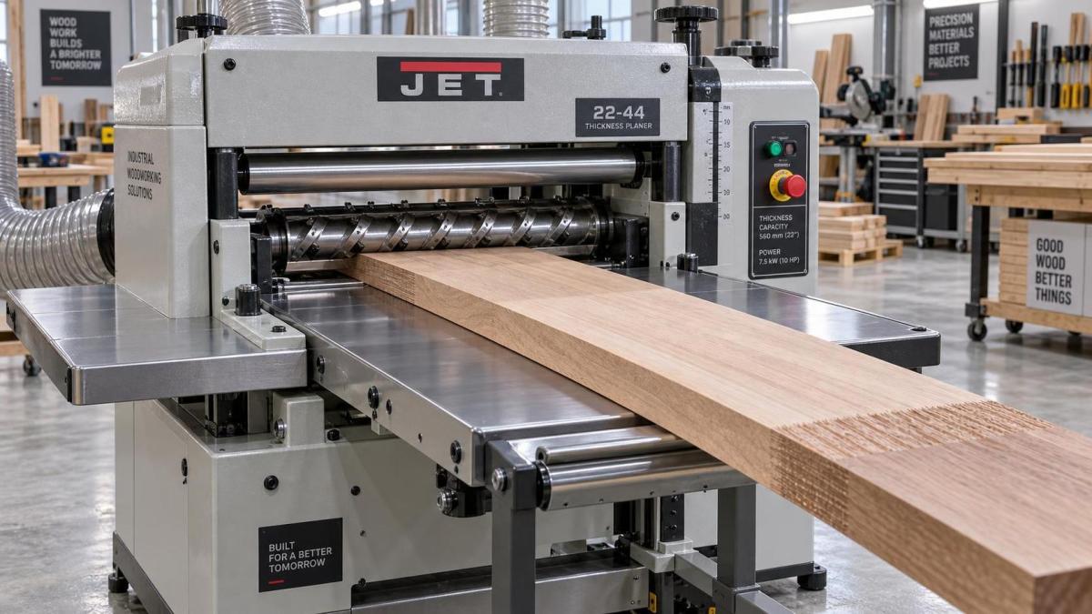
When a board enters the planer, the infeed roller begins applying downward pressure before the outfeed roller fully controls the workpiece. At the moment the leading end passes under the cutterhead, the board can pivot slightly if the infeed table, bed rollers, pressure bars, or feed roller settings are incorrect. The cutterhead then removes more material from the first section of the board.
The same mechanism occurs in reverse at the trailing end. Once the trailing end loses support from the infeed roller, the board may lift or change angle until the outfeed roller has full control. A deeper cut near the exit side is the result.
This is why the location of snipe matters during diagnosis:
- Snipe at the leading end only often points to infeed table height, infeed roller pressure, entry-side bed roller adjustment, or operator support.
- Snipe at the trailing end only more often involves the outfeed table, outfeed roller setting, exit-side support, or a board dropping after it leaves the bed.
- Snipe at both ends suggests a more general feed-path problem, such as tables set below the cutterhead reference plane, excessive feed roller pressure, a loose cutterhead assembly, or an unstable machine base.
- Snipe that varies from board to board can indicate warped stock, uneven stock thickness, inconsistent material handling, resin buildup, or intermittent feed roller traction.
A useful first step is to run a straight, flat test board long enough to remain supported through the full feed cycle. Measure the first and last sections rather than judging by appearance alone. Then repeat the pass while supporting the board at entry and exit. If the defect changes significantly with support, table and feed geometry deserve attention before internal components are adjusted.
Start With Table and Bed Alignment
Extension tables do not need to be dramatically raised to prevent snipe. In fact, setting them too high creates another version of the same problem by forcing the board upward as it approaches or leaves the cutterhead. The aim is a smooth, continuous feed path that keeps the workpiece stable at the cutterhead.
Use a reliable straightedge across the planer bed and extension tables. Check for a low infeed table, a low outfeed table, sagging caused by loose mounting hardware, and movement when hand pressure is applied near the outer end of each table. A table that looks aligned without load may still dip when a heavy hardwood board is introduced.
On many machines, the practical correction is a very slight upward bias at the outer ends of the extension tables. This counteracts natural flex and helps keep the board from dropping at entry or exit. The amount should be small and verified with test cuts. Excessive upward adjustment can cause the board to ride above the intended feed line, producing chatter, feed resistance, or new snipe patterns.
Maintenance personnel should also inspect the machine installation. A planer that rocks on an uneven floor or has an inadequately supported stand can change table alignment during feeding. Tightening table hardware without correcting the base may provide only a temporary improvement.
Feed Rollers and Pressure Bars Must Hold, Not Bend, the Stock
Feed rollers have two jobs: move the board at a stable speed and keep it seated against the planer bed. If roller pressure is too low, the workpiece can slip, hesitate, or lift. If pressure is too high, especially on thin or flexible material, the roller can force the board to follow a distorted path and deepen the cut at the ends.
Do not adjust roller springs by feel alone. Refer to the machine's service specifications for roller height, spring compression, and the relationship between rollers, pressure bars, and cutterhead. The settings are interdependent. Increasing roller pressure may seem to cure a slipping board but can conceal worn rollers, dirty bed surfaces, or an incorrect bed roller setting.
Inspect the following before changing spring tension:
- Feed roller surfaces for glazing, hardened resin, cracks, flat spots, or embedded debris.
- Roller bearings and shafts for drag, uneven rotation, and side play.
- Chain, gearbox, and drive components for irregular feed speed.
- Pressure bar condition and adjustment, where fitted.
- Bed rollers for height consistency and free rotation.
- Planer bed cleanliness and lubricant condition.
Bed rollers require particular care. If they sit too high, the board is carried above the intended reference surface and can rock as it passes under feed pressure. If they sit too low, high-friction stock may drag across the bed, leading to uneven feeding and greater operator force at the entry or exit. Their correct setting depends on the machine design and the material being processed, so service documentation should take precedence over generic adjustment rules.
Check the Cutterhead, Knife System, and Head Locking Mechanism
Snipe is usually a feed-control issue, but cutterhead and head assembly faults can amplify it. Dull or damaged knives raise cutting resistance. This can pull fibers, create a rough finish, and make the workpiece more sensitive to small changes in feed pressure. A board with difficult grain may then show a pronounced defect at the ends even when table alignment is close.
For straight-knife planers, inspect knife projection and clamping consistency across the cutterhead. A knife set unevenly can create a patterned surface defect that may be mistaken for ordinary snipe. For insert cutterheads, check for damaged, loose, or incorrectly seated inserts. Resin accumulation around knife seats or insert pockets can prevent proper seating and affect the quality of cut.
Also examine whether the cutterhead or moving head assembly is stable under cutting load. On thickness planers with an elevating cutterhead, worn column guides, loose gibs, damaged elevation screws, or ineffective head locks can allow slight movement. That movement may be most visible when the workpiece first meets resistance or when the board exits the feed rollers.
A simple diagnostic comparison helps separate these causes. Make a light finishing pass, then repeat with a modestly heavier pass on similar stock. If snipe becomes much worse as cutting load rises, inspect knife condition, feed roller pressure, head locking, and structural play. If the snipe depth remains nearly unchanged regardless of cut depth, extension table geometry and board support are more likely contributors.
Material Condition Can Mislead the Diagnosis
A planer cannot force bowed, twisted, or cupped stock to remain flat against the bed without some movement. When a warped board enters, the feed rollers may temporarily flatten it. After the roller position changes, the board can spring back and alter its relation to the cutterhead. The resulting end defect may resemble a machine setup fault even though the stock is a major factor.
Before making significant mechanical adjustments, test with properly jointed, stable material. Check whether the defect appears on one face only, whether it follows the same physical end after the board is turned, and whether it is worse on narrow or flexible pieces. Thin strips, short parts, and long unsupported boards require more attention to feed support than wide, rigid stock.
Moisture-related movement and internal stress can also complicate results. A board that changes shape after surfacing may appear to have been planed unevenly when the planer actually produced a consistent cut. Measurements should be taken immediately after planing and compared across several boards with similar preparation.
A Practical Correction Sequence
Random adjustment is the fastest way to turn a manageable snipe issue into several interacting faults. A controlled sequence keeps troubleshooting efficient and makes it easier to identify which change solved the problem.
After each adjustment, run the same test board or an equivalent prepared board. Change one variable at a time. This matters because a temporary improvement after several simultaneous adjustments does not establish the real cause, and the machine may return with the same complaint after routine use.
When Snipe Cannot Be Fully Removed
Even a well-adjusted Woodworking Thickness Planer may leave a slight end mark under demanding conditions, especially with short, thin, flexible, or heavily figured material. The objective is to reduce snipe to a controlled level that does not interfere with the finished part, while maintaining reliable feed and safe handling.
For production work, allow reasonable extra length where part design permits, then trim the affected ends after planing. For components that cannot be overlength, use carrier boards, continuous-feed methods, or carefully matched support at the infeed and outfeed sides. These methods should supplement a properly adjusted machine, not compensate for loose tables, worn rollers, or an unstable cutterhead assembly.
The repair is complete when repeated test boards show a consistent finish across the usable length, feed remains smooth without excessive roller force, and the result holds after normal cutting loads are restored. That standard is more useful than chasing a visual improvement on one favorable board.
Send Your Inquiry
We welcome your cooperation and we will develop with you.