


News & Exhibitions
Latest Factory Updates, Industry Trends & Global Exhibition Information
Troubleshooting Hinge Cup Misalignment on CNC Hinge Milling Machines
Hinge cup misalignment should be isolated before any machine-wide adjustment is made. A cup drilled consistently 1 mm away from its intended location points to a different fault than a cup whose position changes from panel to panel. Begin by separating repeatable positional error, variable positional error, and apparent misalignment caused by the hinge or door. This prevents a simple datum or program issue from being mistaken for a spindle, servo, or frame problem.
Use a flat sample panel with a clearly identified reference edge. Run the same hinge pattern several times without changing the workpiece datum, then measure the cup center from the reference edge and from the panel end. Record both the X and Y result, along with cup depth and any breakout around the rim. A stable offset in every sample usually originates in the coordinate system, program, fixture stop, or tool geometry. A changing result requires closer attention to clamping, material movement, spindle condition, axis backlash, and contamination at contact surfaces.
Start With the Error Pattern
The direction of the error carries useful diagnostic information. If every cup is too close to the door edge by the same amount, inspect the programmed edge offset, the selected machining side, and the panel stop. If the first cup is correct but the second or third cup drifts along the length of the door, look at axis positioning, workpiece slip, or a program that calculates spacing from the wrong reference point.
A cup that is correctly located at entry but appears shifted at the bottom needs a different investigation. That pattern often comes from tool deflection, spindle runout, a bent boring bit, or a loose spindle assembly. It can also occur when the material surface is not held flat against the fixture: the bit enters at an angle relative to the panel, so the visible rim and the bottom of the pocket do not share the same center.
Verify the Datum Before Editing the Program
Many hinge drilling complaints are created by a mismatch between the drawing datum and the physical datum used on the machine. A program may define cup centers from the left edge, while the panel is loaded against a right-hand fence after a mirrored door sequence. The numerical values can appear correct on screen and still place every cup on the wrong side of the intended reference.
Confirm which edge is treated as X zero and which end is Y zero for the active job. Then verify the actual panel orientation, face side, and handedness. Door parts are especially vulnerable to this error because a left-hand and right-hand component can use the same dimensions but require mirror-image hinge positions. Do not rely only on a label or job name; compare the selected work coordinate to a marked physical reference on the test panel.
Tool offset data deserves the same scrutiny. If the control compensates the cup center from a tool diameter value, an incorrect value shifts the path or changes the relation between pilot drill and cup cutter. For a fixed-pattern boring head, verify that the control is using the intended head configuration rather than an offset inherited from another tooling setup. Editing the coordinate values to compensate for an uncertain offset can conceal the original fault and create further problems when the correct tooling is restored.
Program details that produce convincing but wrong results
Imported hinge patterns sometimes contain a center-to-edge distance that is valid only for a particular hinge cup diameter or mounting plate arrangement. The hole may be accurately machined to its programmed coordinate while the assembled hinge makes the door appear incorrect. Before changing machine parameters, verify the hinge specification, cup diameter, cup depth, and required setback from the door edge.
Also inspect unit selection and decimal interpretation when jobs move between systems. A gross error is easy to spot; a small conversion issue or an incorrectly rounded offset can remain unnoticed until doors are assembled. Run a dry coordinate verification or mark positions with a non-cutting tool path where the control supports that function. The aim is to confirm commanded centers against the drawing without the cutting process influencing the result.
Fixture Contact Is Part of the Coordinate System
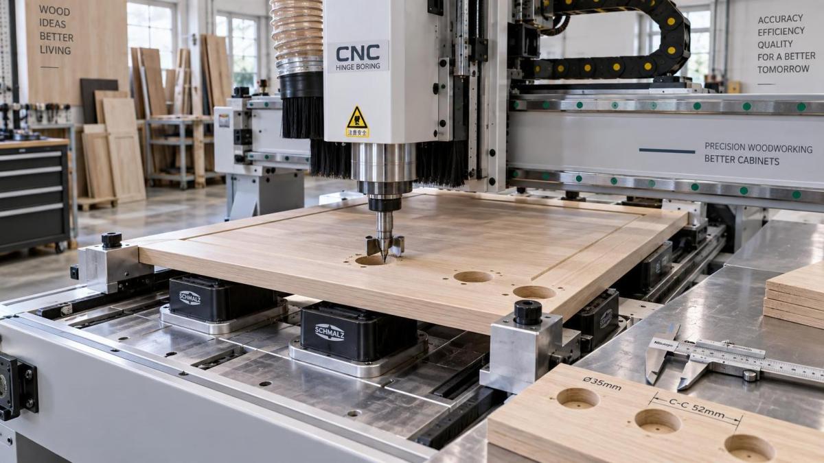
A precise CNC Hinge Milling Machine cannot repeat a position that the panel itself does not repeat. Chips under a panel edge, compressed dust on a locating stop, or adhesive residue on a vacuum pod can change the part position enough to affect hinge fit. This is particularly common with melamine-faced board and coated panels, where fine debris remains on smooth contact surfaces instead of embedding into the material.
Clean the fence, locating pins, vacuum cups, and underside of the test panel. Inspect stop faces for dents, loose fasteners, or a buildup that prevents full seating. A worn retractable stop can move under the load of panel placement and then return, leaving no obvious indication after the cycle. If the fault occurs only on longer or heavier doors, observe whether the panel is being pressed squarely into all reference surfaces before clamping begins.
Vacuum clamping requires more than adequate pump sound. A blocked cup, damaged gasket, leaking hose, or porous panel surface can allow the workpiece to creep during the plunge. The resulting error is often inconsistent and may be accompanied by scuffing, a raised rim, or a slight directional smear at the cup edge. Mark the panel outline on a sacrificial backing surface before machining. Any movement relative to that mark identifies a holding problem without requiring assumptions about the axis system.
Panel flatness changes the diagnosis. A bowed door can touch the fence at one point while lifting away from a support area. When clamped, it may flex into a different position than when measured on a bench. Check the reference face for twist and bow, especially after storage changes or when processing solid wood components. For solid wood, grain direction, moisture variation, and stress released by prior shaping can alter flatness between operations. Profiling on a Spindle Moulder should be followed by a flatness and reference-edge check before hinge drilling, since the hinge pattern is only as reliable as the surfaces used to locate the door.
Examine the Cutting Assembly Separately From Positioning
Do not judge spindle accuracy solely by whether the machine reaches the commanded coordinate. A worn or damaged cup cutter can pull sideways as it enters the board. Uneven cutting edges, packed resin, missing carbide, or an incorrectly assembled cutter create unequal cutting forces. The rim may look circular from a distance while the actual center at depth is displaced.
Remove the tool and inspect the shank, cutter body, collet, and taper contact surfaces. Resin or dust trapped in the collet changes seating and can introduce runout even when the tool appears tight. Clean components with a suitable method, reassemble them correctly, and measure runout at a practical distance from the spindle nose and again near the cutting length. A reading at only one location may miss a bent bit.
Different materials reveal different symptoms. MDF often exposes heat, dullness, and chip packing through fuzzy or darkened walls. Particleboard can break out around the rim, making a correctly located cup look offset. Hardwood can deflect a dull bit more noticeably because cutting resistance changes with grain direction. Use a known-good sharp tool and a stable sample material before attributing the fault to servo motion.
Depth must also be confirmed. An excessively deep cup can weaken the door face and make the hinge sit unevenly, which is sometimes reported as a location error. A shallow cup prevents the hinge from seating fully and shifts the visual relationship between the hinge arm and mounting plate. Measure depth from the actual reference face, not from a compressed chip layer or a rough cut rim.
Test Axis Repeatability With a Simple Pattern
Once datum, fixture, and tooling have been verified, test the machine axes using a pattern that removes hinge hardware from the equation. Bore or mark a row of points at equal intervals along one axis, then return to the starting point and repeat. Measure spacing between point centers rather than measuring only from an external panel edge. Center-to-center measurements reveal whether the machine is accumulating position error across travel.
If the first and last positions are wrong by a similar amount while the intermediate spacing remains correct, the work zero or fixed reference is more suspect than axis scaling. If each subsequent point becomes progressively farther from nominal, inspect the axis transmission and feedback system. Loose rack engagement, belt tension problems, coupling slip, contaminated encoder components, or a ballscrew issue can produce cumulative displacement. The exact design determines the inspection method, so use the machine documentation before altering backlash or servo parameters.
Backlash tends to show itself when the axis approaches the same coordinate from opposite directions. Program a test that approaches a location from positive travel and then from negative travel, using safe clearance moves. A difference between the two results indicates lost motion or a control compensation issue. Do not compensate electronically until mechanical fasteners, drive components, guides, and lubrication condition have been examined. Compensation cannot secure a loose coupling or repair a worn transmission element.
Mechanical alignment and Z-axis effects
A loose boring head mount, damaged linear guide, or spindle carriage that shifts under plunge load can create a fault that changes with depth and feed. Listen for unusual vibration, but confirm it with a measurement where possible. With power isolated according to the machine procedure, inspect fasteners, carriage interfaces, and guard clearances for evidence of movement. Look for polished witness marks, displaced paint, or recurring contact marks around the tooling area.
For Z-axis checks, place a suitable indicator arrangement on a rigid reference and observe repeatability at the same commanded height. Repeat the test after several Z movements. A depth variation combined with lateral cup variation often means the tool is entering under changing load or the panel is not consistently supported. A depth-only issue does not automatically explain an X-Y shift, so avoid combining separate faults into one adjustment.
Restore Accuracy Through Controlled Corrections
Make one correction at a time, then repeat the same test panel and measurement method. Changing the fixture, tool, work offset, and servo setting together may produce an acceptable sample without establishing why the error disappeared. That approach becomes expensive when the same symptom returns on a different door size or material.
- Establish a marked reference panel and document the commanded cup centers, actual centers, depth, panel orientation, and tooling used.
- Correct physical seating and holding defects before modifying offsets. Recut the test panel only after the locating surfaces are clean and the workpiece is stable.
- Install verified tooling and confirm spindle runout, then repeat the pattern to distinguish cutting deflection from coordinate error.
- Investigate axis repeatability and mechanical transmission only when the error persists with a stable datum and known-good tool.
- After adjustment, machine samples at the near end, middle, and far end of normal travel, including both handed door programs where applicable.
Keep the final verification tied to assembly. A dimensionally correct cup can still produce poor door alignment if the wrong hinge, mounting plate height, or screw location is used during fitting. Fit a confirmed hinge to the test door, mount it to a correctly prepared cabinet member, and evaluate reveal, depth, and side adjustment. This final step distinguishes a machining fault from an installation mismatch without changing a machine that is already positioning correctly.
Stable hinge cup positioning comes from preserving the entire reference chain: a valid program datum, a panel seated against clean and rigid locators, sound clamping, a true cutting assembly, and axes that return to position. When measurements identify where that chain breaks, calibration becomes a precise repair rather than a series of compensating guesses.
Send Your Inquiry
We welcome your cooperation and we will develop with you.