


News & Exhibitions
Latest Factory Updates, Industry Trends & Global Exhibition Information
What causes snipe on a double sided planer and how can it be reduced?
Snipe on a Double Sided Planer can quickly turn accurately machined boards into costly rework, especially when it appears at leading or trailing workpiece ends.
For after-sales maintenance teams, the priority is determining whether snipe comes from setup, wear, alignment, material handling, or an underlying mechanical fault.
In most cases, planer snipe is not caused by one isolated component. It results when workpiece support and feed pressure change during entry or exit.
This guide explains how maintenance personnel can diagnose snipe systematically, correct common faults, and help customers maintain smoother, more consistent production results.
What Is Snipe on a Double Sided Planer?
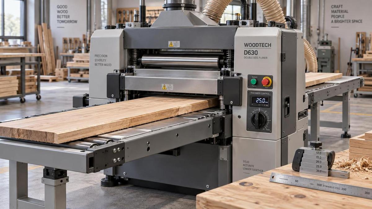
Snipe is a localized variation in thickness or surface depth near the beginning or end of a board after it passes through a Double Sided Planer.
It may appear as a shallow depression, a deeper cut, or an uneven transition. Even small defects can be unacceptable for furniture panels and precision components.
On a double sided machine, snipe can occur on the upper surface, lower surface, or both surfaces at the same time.
The defect is usually most visible after sanding, staining, coating, or panel assembly. These later processes often make thickness variation more obvious and costly.
Maintenance teams should first confirm that the issue is true snipe rather than knife marks, chatter, belt slip, stock warping, or inconsistent material thickness.
Measure affected boards at several points using a calibrated thickness gauge. Compare the leading end, center section, and trailing end before adjusting machine components.
A repeatable thickness loss at both ends usually indicates support or pressure changes. Random defects more often point to unstable material, feed problems, or damaged tooling.
Document the board species, width, length, moisture condition, target thickness, feed speed, and cutterhead settings before beginning a detailed inspection.
Why Leading-Edge Snipe Happens During Board Entry
Leading-edge snipe occurs when the front of the workpiece enters the Double Sided Planer and is not yet supported by enough feed rollers.
At entry, the board may pivot slightly around the first contact point. This movement changes its relationship with the lower cutterhead, upper cutterhead, or pressure elements.
If the infeed table is too low, the board can rise or dip as it reaches the first driven roller. The cutter then removes extra material.
An infeed table that sits too high can also create an abrupt transition. The board may flex downward as it crosses onto the machine bed.
Incorrect infeed table alignment is especially common after transportation, machine relocation, collision damage, or incomplete reassembly following service work.
Check table flatness and height against the manufacturer’s specified reference plane. Use a straightedge, dial indicator, and appropriate measuring blocks where required.
Do not rely only on visual checks. Small height differences can produce visible snipe when processing long boards, narrow strips, or material with limited stiffness.
Worn, contaminated, or weak first feed rollers can worsen leading-edge snipe because they fail to stabilize the board before cutting begins.
Inspect roller surfaces for resin buildup, flattened areas, damaged coating, bearing play, uneven spring pressure, and insufficient traction across the working width.
Why Trailing-Edge Snipe Develops at Board Exit
Trailing-edge snipe usually appears when the last portion of the board leaves the final feed roller or loses stable support near the outfeed side.
As roller contact changes, the workpiece can pivot or lift slightly. That movement changes cutting depth during the final seconds of the planing pass.
An outfeed table set below the machine reference plane allows the board end to drop. This often causes deeper cuts near the trailing edge.
If the outfeed table is too high, the board may be forced upward during exit. Depending on machine geometry, this can also produce a visible thickness variation.
Verify that the outfeed table supports the finished board at the correct height. The setting must match the machine manufacturer’s documented adjustment method.
Long, heavy, flexible, or wide boards need particular attention. Their unsupported mass can pull the trailing end down even when the planer itself is correctly adjusted.
Customers sometimes report intermittent snipe only on longer workpieces. In those cases, inspect external roller supports and operator handling before replacing machine parts.
Outfeed roller wear can also cause instability. Check roller concentricity, surface condition, pressure adjustment, bearing smoothness, and synchronization with adjacent rollers.
When a trailing defect appears only on one side of the board, compare left and right roller pressure, table support, cutterhead position, and frame alignment.
How Feed Roller Pressure Affects Planer Snipe
Feed rollers hold the workpiece firmly against the machine reference surfaces. Their pressure must be sufficient for control without compressing or distorting the material.
Too little pressure allows the board to move as cutter forces change. Too much pressure can compress softwood and create inconsistent thickness after recovery.
On a Double Sided Planer, pressure settings must be coordinated with cutting depth, board species, moisture content, surface roughness, and feed speed.
Maintenance personnel should compare actual roller spring compression or pneumatic pressure with the equipment manual, rather than adjusting based solely on operator preference.
Uneven pressure from one side to the other can cause a board to tilt. This may create snipe, taper, or different surface quality across the width.
Check pressure roller shafts for binding, damaged springs, leaking cylinders, worn bushings, and accumulated dust that restricts normal vertical movement.
Roller surfaces should be clean and free from oil, wax, glue residue, and compacted wood fibers. Contamination reduces grip and makes feed behavior unpredictable.
Also inspect the feed transmission system. Loose chains, worn gears, damaged universal joints, or variable-speed drive faults can create inconsistent board movement through the cutterheads.
Any adjustment should be followed by test passes using the customer’s typical material dimensions. A setting that works on short hardwood pieces may fail on long softwood panels.
Could Cutterheads, Knives, and Pressure Bars Be Responsible?
Cutterhead problems do not always create classic snipe, but they can make entry and exit defects worse by increasing cutting force or reducing surface consistency.
Dull knives require more force to remove material. The extra resistance can pull a poorly supported board upward, downward, or sideways during critical transitions.
Inspect knife sharpness, knife projection, insert seating, locking hardware, and cutterhead balance. Replace damaged knives or inserts as a matched set when necessary.
On conventional knife cutterheads, uneven knife height can cause periodic marks that may be mistaken for snipe. Use the correct setting gauge and procedure.
Helical cutterheads require different inspection practices. Confirm that inserts are seated correctly, fasteners are tightened to specification, and damaged edges are indexed or replaced.
Pressure bars are equally important because they control the workpiece near the cutting zone. Incorrect clearance can allow movement before or after the cut.
A pressure bar set too high may not restrain the board effectively. A bar set too low may mark material, overload feed rollers, or cause unnecessary friction.
Check upper and lower pressure elements separately. A double sided configuration can have different symptoms depending on which cutterhead and support system is involved.
Never adjust pressure bars without referring to the specific machine documentation. Generic settings can be unsafe and may produce poor results on another planer design.
How Table Alignment and Machine Geometry Should Be Checked
Stable table geometry is the foundation for reducing snipe. Even well-maintained rollers cannot fully compensate for an infeed or outfeed table that is misaligned.
Begin with a clean machine. Remove chips, resin, adhesive, damaged wear strips, and loose debris that could affect measurements or board support.
Lock all adjustable components according to the service procedure. Measurement results are unreliable when tables, heads, rollers, or pressure assemblies are not secured properly.
Use precision instruments appropriate for the tolerance required. A long straightedge, feeler gauges, dial indicators, and magnetic bases are common service tools.
Measure table height at the left, center, and right sides. Repeat measurements along the board travel direction to identify twist, sag, or uneven mounting points.
Check whether the outfeed support follows the finished workpiece path. Its effective plane should support the board without forcing it away from normal machine geometry.
Inspect machine anchors and the floor condition. A poorly leveled machine or loose foundation bolts can allow frame distortion, especially after relocation or heavy operation.
For machines with automated thickness positioning, inspect lift screws, chains, guide columns, encoder feedback, and synchronization between left and right lifting systems.
Unequal elevation movement can cause thickness variation across the board width. It may be reported as snipe when operators inspect only short sections near board ends.
What Operating Practices Can Reduce Snipe Immediately?
Correct maintenance settings are essential, but operating practice still affects results. Customers should be given clear handling guidance after any mechanical service visit.
Feed boards straight into the machine without lifting the leading edge. Operators should support long workpieces while allowing rollers to control final positioning.
At the exit side, support the finished board level with the outfeed plane. Do not pull downward, lift upward, or twist the board before feed rollers release it.
Use properly sized infeed and outfeed support tables for long material. Adjustable roller stands can help, but their height must be checked carefully.
Avoid processing severely warped, twisted, cupped, or bowed stock without considering how it contacts the machine reference surfaces. Unstable stock can mimic equipment faults.
Reduce excessive cutting depth when processing difficult materials. Heavy stock removal increases cutting load and makes movement at entry and exit more likely.
Feed speed should also match material and cutting conditions. Very high speed can reduce effective control when knives are dull or feed components are worn.
For short pieces, follow the machine’s minimum workpiece length requirements. Material shorter than the supported roller span may be unsafe and prone to severe snipe.
When possible, leave extra trimming allowance at each end of critical boards. This is a practical production safeguard for components requiring flawless finished lengths.
A Practical Troubleshooting Sequence for After-Sales Teams
A structured diagnosis prevents unnecessary parts replacement. Start by confirming the defect pattern using multiple boards of the same material and operating condition.
Record whether snipe occurs at entry, exit, both ends, one surface, both surfaces, one side, or across the full width of the workpiece.
Next, inspect basic operating factors: board length, support method, cutting depth, feed speed, moisture condition, stock straightness, and cutter tool condition.
Then clean the machine and inspect all accessible feed rollers, pressure bars, table surfaces, springs, bearings, pneumatic lines, and drive components.
Measure infeed and outfeed table alignment against the manufacturer’s reference points. Correct gross errors before making fine roller or pressure-bar adjustments.
Check roller pressure and height in the documented adjustment order. Changing several settings simultaneously makes it difficult to identify the actual source of improvement.
Run controlled test pieces after each adjustment. Mark every board with the setting change, pass direction, machine side, and measured thickness results.
If symptoms remain, inspect cutterhead geometry and machine lifting systems. Use the service manual tolerances and escalate to factory technical support when required.
For global customers, Qingdao Zhongding Machinery can provide technical guidance, spare parts support, and troubleshooting assistance for woodworking machinery maintenance needs.
Conclusion: Reduce Snipe by Controlling Support and Feed Stability
Snipe on a Double Sided Planer is usually a support and stability problem occurring when roller contact, table support, or cutting forces change.
The most effective corrective approach is systematic: verify the defect, inspect material handling, clean and check feed components, measure table geometry, then test adjustments.
Leading-edge snipe commonly points to infeed support and initial roller control. Trailing-edge snipe more often involves outfeed support and final roller contact.
Well-maintained cutterheads, correctly adjusted pressure bars, clean rollers, aligned tables, and disciplined operating methods reduce rework while improving finished-board consistency.
For after-sales teams, accurate diagnosis matters more than quick adjustment. A documented troubleshooting process protects machine performance, customer confidence, and long-term production efficiency.
Send Your Inquiry
We welcome your cooperation and we will develop with you.