


News & Exhibitions
Latest Factory Updates, Industry Trends & Global Exhibition Information
How to choose wood product cutting machinery for clean edges
Clean edges are not produced by a single machine specification. They result from a controlled relationship between the cutting process, the material being cut, the tool geometry, panel support, feed motion, and dust removal. A high-speed machine with an unsuitable blade or unstable workpiece support can create more defects than a modestly rated machine configured correctly for the production mix.
For technical evaluation, the central question is not “Which wood product cutting machinery is fastest?” It is whether the machine can repeatedly produce the required edge quality on the actual boards, thicknesses, coatings, cut directions, and batch sizes used in production. The required standard may range from a paint-ready edge to a near-chip-free melamine cut that can move directly to edge banding. Those are different requirements and should lead to different machine configurations.
Define “clean edge” before comparing machinery
Edge quality is often described too broadly. In practice, the defect to be avoided matters more than the general requirement for a smooth cut. On veneered panels, the main concern may be veneer breakout at the exit side. On melamine-faced chipboard, it may be chipping on both the top and bottom decorative surfaces. Solid wood components introduce grain tear-out, burn marks, fuzzy fibres, and variation between boards. Plywood can delaminate at the cut line if the blade, feed, and support conditions are wrong.
A machine should therefore be assessed against a defined acceptance condition. Useful criteria include:
- Maximum permissible chip size on visible faces;
- Whether the edge must be ready for edge banding, painting, or direct assembly;
- Allowed dimensional deviation and squareness over the part length;
- Surface condition of the cut wall, including saw marks and fibre pull-out;
- Consistency from the first panel to the last panel of a production run.
Without this definition, evaluations can be distorted by demonstrations on easy material or short trial cuts. A machine that cuts raw MDF cleanly may not maintain the same result on double-sided laminated particleboard, high-pressure laminate, plywood, or solid timber with difficult grain.
Match the cutting principle to panel format and defect risk
Different cutting machines solve different production problems. Selecting by nominal cutting capacity alone ignores where the edge defect originates.
Sliding table saws remain practical for flexible workshops, smaller batches, angled work, and operations where the operator must control positioning. Their edge quality depends heavily on carriage rigidity, fence accuracy, scoring arrangement, blade selection, and operator handling. A well-set sliding saw can give excellent results, but output consistency is more sensitive to setup discipline than on automated panel equipment.
Beam saws are designed for repeated panel sizing, particularly where sheet handling, programmed dimensions, and throughput are important. The clamping beam and controlled saw travel can improve repeatability. For laminated panels, a scoring saw is often essential to protect the lower decorative face. The machine should be evaluated not only on its main saw motor but also on clamp pressure distribution, panel support, scoring synchronization, and the repeatability of pusher positioning.
Panel saws with nested CNC routing offer different advantages. A router can cut complex shapes, internal cut-outs, and mixed part geometries in one program, but a routed edge does not always equal a saw-cut edge. Tool runout, cutter condition, chip load, vacuum hold-down, and toolpath direction strongly affect edge finish. Nested routing is suitable where shape flexibility is the governing need; it should not be assumed to be the best choice for every straight-cut, high-volume panel application.
Optimizing crosscut saws and moulders are more relevant to solid timber processing. Their performance must be judged in relation to moisture variation, grain direction, stock straightness, and defect detection. A clean crosscut on straight, dry timber may become unreliable when boards have cup, twist, internal stress, or variable density.
The spindle-and-blade system is the primary edge-quality system
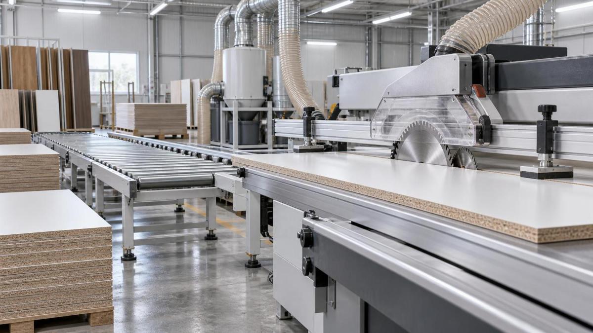
Machine rigidity matters, but it cannot compensate for a poor cutting tool system. The blade or cutter must suit the board construction, coating hardness, cut depth, machine speed, and target finish.
For panel saws, blade tooth geometry, tooth count, kerf, hook angle, and coating all influence cut quality. A fine-tooth blade may reduce surface chipping but can generate heat if feed is too slow. A more aggressive tooth form can maintain productive feed rates but may increase breakout in fragile surface layers. There is no universally correct blade: a blade suitable for raw MDF is not automatically appropriate for high-gloss coated board or veneer-faced plywood.
On laminated panels, scoring is often treated as an accessory rather than a matched cutting operation. It should be evaluated as a system with the main blade. The scoring kerf must align precisely with the main blade kerf; if it is too narrow, it cannot protect the surface. If it is too wide, a visible score line may remain. Height adjustment also matters because insufficient score depth allows chips to persist, while excessive depth can weaken the edge or leave an unnecessary mark.
For CNC routers, radial and axial runout deserve close attention. Even a high-quality compression cutter will leave a poor edge if the spindle taper, collet, tool shank, or bearing condition introduces measurable runout. Compression tooling can reduce chipping on both panel faces once the cutting geometry is fully engaged, but plunge entry, shallow passes, and through-cut strategy must be considered. Downcut, upcut, compression, and straight-flute tools each create different forces and finish characteristics.
Tool maintenance should be part of the machinery assessment. The relevant issue is not simply whether replacement blades are available. The machine should permit repeatable blade changes, practical scoring alignment, safe access, and a clear method for returning to the qualified setup. A cutting cell that requires lengthy trial adjustments after each blade change can undermine its theoretical production capacity.
Feed stability determines whether the chosen tool can work correctly
Cutting tools need a stable chip load. If feed rate fluctuates, the edge can alternate between smooth sections, burnishing, and chip-out even when spindle speed remains constant. This is why feed design is as important as motor power.
On a panel saw, assess whether rollers, grippers, clamps, or the pusher hold the board without allowing lateral movement. Thin panels, narrow strips, bowed sheets, and small components are particularly revealing test pieces. A machine may process a full-size panel accurately but perform poorly once it begins producing narrow cabinet parts.
For solid wood, feed rollers must maintain contact without crushing softer material or allowing the workpiece to lift into the cutter. The relationship between feed speed and cutterhead speed should be checked at the intended production rate, not only at a reduced demonstration speed. Excessive speed can produce torn grain; excessively slow feed can darken the cut edge through heat buildup.
Vacuum hold-down on nesting equipment requires equal scrutiny. Sheet flatness, spoilboard condition, vacuum zoning, gasket integrity, and cutting sequence all influence whether a part remains stable near the end of the toolpath. Small pieces can shift after they are almost completely cut free, damaging the final edge or creating a safety risk. Onion-skin strategies, tabs, or dedicated small-part handling may be necessary, but each can add a secondary finishing operation.
Machine structure and alignment affect more than dimensional accuracy
Clean edges depend on the cutting tool entering and leaving the workpiece predictably. Structural vibration, spindle bearing wear, loose sliding mechanisms, and insufficiently rigid saw arbors can leave repeating marks or cause intermittent chipping. These defects are sometimes blamed on the blade because they appear as a surface problem, but their pattern may point to a mechanical issue.
During technical review, it is useful to inspect the following conditions under load rather than relying solely on catalogue tolerances:
- Spindle or arbor runout and bearing condition;
- Parallelism of saw blade, sliding carriage, fence, pressure beam, and scoring unit;
- Repeatability of digital stops, pushers, and servo-driven positioning systems;
- Rigidity of moving assemblies at the intended feed speed;
- Ability to maintain squareness on long and narrow parts;
- Adjustment access and the risk of setup drift after routine maintenance.
A useful acceptance trial includes the production materials that create the highest defect risk, not only standard sample boards. Cut both full panels and narrow strips. Make crosscuts and rip cuts where relevant. Inspect the first and last components from a sequence, because heating, dust accumulation, and positioning drift may not be visible in a single cut.
Dust extraction is part of the cut, not a separate utility decision
Wood dust and chips that remain in the cutting zone can be recut, dragged across a decorative face, or compacted near guides and clamps. The result may be edge damage, surface scratches, heat, reduced visibility, and accelerated tool wear. Fine dust from MDF and similar engineered boards is especially demanding because it can collect in machine cavities and interfere with moving components.
Evaluate the extraction connection size, hood design, air path around the blade or cutter, and access for cleaning. The machine’s extraction requirement must also be compatible with the available dust collection system. A high-performing saw connected to insufficient airflow will not consistently reproduce its initial finish quality. Where laminated panels are processed, extraction also affects cleanup around scoring mechanisms and pressure devices, where compacted debris can gradually alter alignment.
Extraction performance has a safety dimension as well. The machinery installation must be designed around applicable local workplace safety and dust-control requirements. Technical approval should verify the machine documentation, electrical compatibility, guarding, emergency stopping arrangement, and intended extraction configuration for the destination market rather than assuming that a generic machine specification covers every installation condition.
Material handling can damage edges after a perfect cut
An edge may leave the blade clean and still arrive at the next process damaged. This is common with coated boards, narrow strips, long cabinet sides, and heavy panels. Unsupported outfeed sections can allow a panel to drop slightly at the end of a cut. Manual stacking can chip corners. A roller that is contaminated with abrasive dust can mark a finished surface.
Evaluate infeed and outfeed support as part of the machine cell. For heavy sheet goods, loading method and table height influence whether the panel remains flat during entry. For small parts, controlled collection prevents components from colliding after separation. If the intended process connects cutting directly to edge banding, buffer capacity and part identification need attention; rushed manual handling can erase the quality benefit achieved at the saw.
Edge banding is also where a cutting quality problem becomes commercially visible. Glue line consistency, trimming performance, and corner finish all depend on the panel edge being straight, square, and free from substantial breakout. A finishing machine cannot fully correct a deeply chipped substrate edge without reducing final part dimensions or leaving a weak bond area.
Where straight cabinet and furniture components move from sizing into finishing, an automatic edge bander such as the Straight Automatic Edge Banding Machine ZD450C can be assessed as a downstream process rather than a substitute for accurate cutting. Its stated 10–60 mm working thickness range and 0.4–3 mm edge thickness range illustrate why interface checks matter: panel thickness, edge material, feed direction, and cut-edge condition must fit both machines. Automatic feeding, gluing, trimming, and polishing can support a consistent sequence only if the upstream cut dimensions and edge integrity are controlled.
Do not use speed as a proxy for productivity
A faster cutting cycle is productive only when it does not increase rework, tool changes, sorting, or edge repair. The relevant comparison is finished acceptable output at the required quality level. This includes setup time, programming time, blade change frequency, offcut management, material movement, cleaning, and the time required to recover after a misaligned scoring blade or damaged cutter.
For low-mix, repeated panel sizing, automation may reduce variation and handling time. For mixed batches with frequent size changes, a simpler machine with rapid, reliable adjustment may deliver better effective output than a highly automated line that requires complex setup. Complex machining should be justified by the workpiece range and the control needed, not selected merely because it offers more functions.
Serviceability should be evaluated in the same practical way. Ask which components require regular inspection, whether wear settings can be verified without major disassembly, what diagnostic information is available, and whether spare parts can be identified unambiguously. Electrical diagrams, operating manuals, tooling specifications, lubrication requirements, and remote support arrangements affect how quickly a machine can be returned to a qualified cutting condition.
A more reliable evaluation method
The strongest machine comparison is based on a documented sample-cut protocol. Supply representative boards, including the most demanding finish and thickness. Set a realistic production feed rate. Specify the tool and scoring configuration. Measure dimensions and squareness, then inspect edges under consistent lighting and magnification appropriate to the product’s visible quality standard.
Record not only the result but the settings used to achieve it: blade type, spindle speed, feed speed, scoring width and depth, clamp settings, extraction condition, and operator adjustments. If a supplier demonstration depends on unusually slow feeding, special tooling unavailable in routine operation, or repeated manual correction, that dependency should be treated as part of the machine’s operating requirement.
The right wood product cutting machinery is the one that maintains clean edges under defined operating conditions, with tooling and material handling that can be sustained on the shop floor. Clean cutting is not a headline feature. It is a repeatable process capability, and the evaluation should test every part of the process that can disturb it.
Send Your Inquiry
We welcome your cooperation and we will develop with you.