


News & Exhibitions
Latest Factory Updates, Industry Trends & Global Exhibition Information
How an Automatic Beam Saw Positions and Cuts Panel Stacks
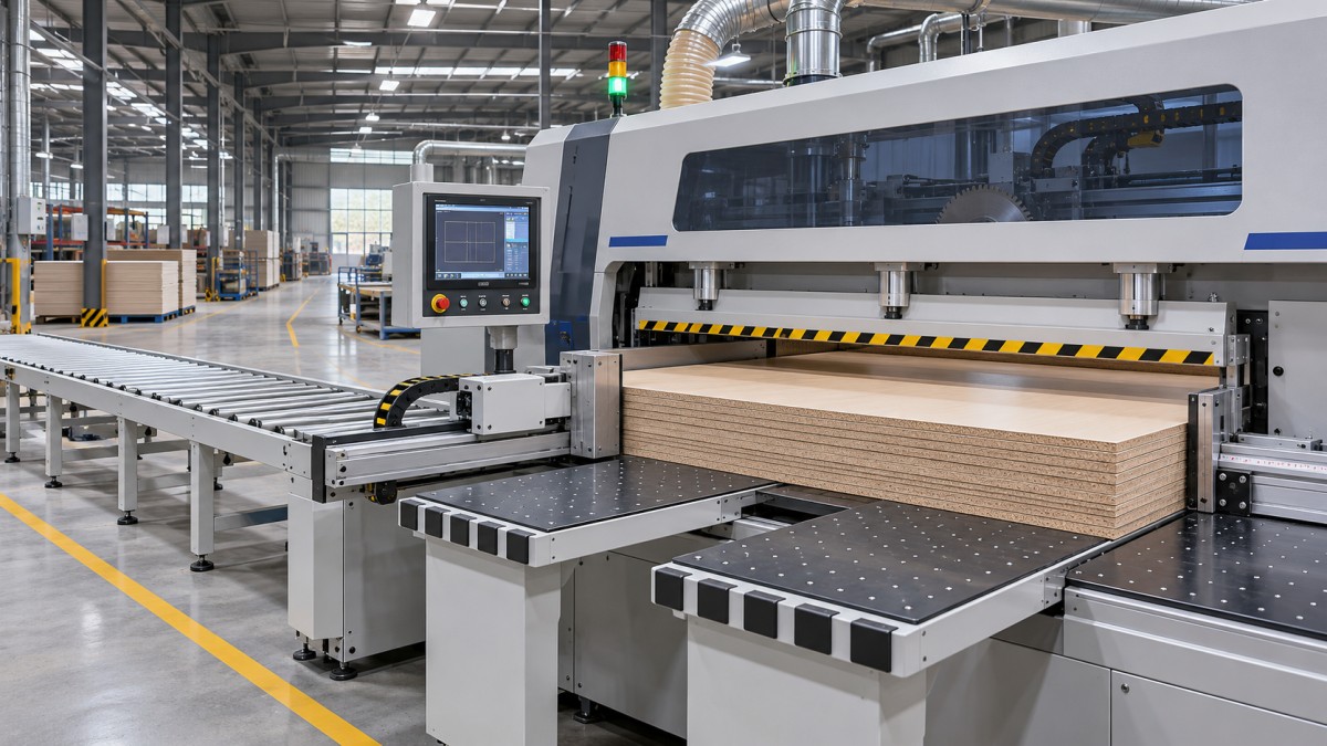
An automatic beam saw positions a stack by establishing a reference edge, feeding the material to a programmed cut line, and holding the panels down while a saw carriage travels across them. The feed mechanism then advances the remaining stack for the next cut. Each movement depends on the previous one: a precisely controlled pusher cannot compensate for panels that were misaligned before clamping or shifted during the cut.
For a technical evaluator, the useful question is how consistently the machine maintains the relationship between the reference edge, the programmed position, and the blade under production conditions. Stack height, panel flatness, clamp pressure, blade setup, and the cutting pattern all affect that relationship. Understanding the sequence makes it easier to distinguish a positioning specification from the accuracy that can be expected across a complete batch of parts.
From panel stack to first cut
The cycle starts with the panels placed on the machine’s infeed table or loading system. Depending on the configuration, loading may be manual, assisted, or integrated with automated handling equipment. The stack must sit within the machine’s supported working area, with its leading and side edges positioned so the feed and alignment mechanisms can establish a repeatable starting point.
Panels in a stack do not automatically behave as one solid workpiece. Sheets can have small differences in length, width, flatness, and edge condition. If the bottom sheet rests against a reference while an upper sheet projects beyond it, the same blade pass will remove a different amount from each sheet. Operators therefore need a loading method that brings the relevant edges into alignment without trapping debris between panels or damaging finished surfaces.
A side alignment device may press the stack toward a fixed reference fence before or during positioning. The feed system then controls movement along the direction in which cut widths are set. The exact arrangement varies by machine: some use powered pushers or grippers, while others combine these functions with automated loading and alignment equipment. Evaluators should establish which devices are included and which reference surfaces they use.
For a rectangular cutting pattern, the first operation may be a trim cut. Removing a narrow strip creates a fresh reference edge, provided the stack is held securely and the resulting edge is suitable for the following operations. A trim cut cannot correct every loading error: if sheets are displaced relative to one another or the stack moves during cutting, the newly cut edges may still fail to provide the intended common reference.
How the machine sets each cut position
The controller converts the cutting program into a sequence of feed positions and saw movements. In a common arrangement, a programmed pusher moves the stack toward the saw line. Its drive system and position feedback control how far it travels, while grippers or a pushing face maintain contact with the material. After a cut, the machine advances the remaining stack to position the next strip.
The relevant dimension is the distance between the active reference and the saw blade’s cutting plane. The control system must account for blade kerf—the width of material removed by the cut—when calculating successive positions. Depending on the machine and program, it may also account for an initial trim and other programmed allowances. Evaluators should understand how the control handles these values and how changes to blade or cutting setup are entered.
Good positioning depends on more than the drive’s stated resolution. A loose gripper, a stack that slips against the pusher, play in a mechanical drive, or an incorrectly set saw line can all produce parts that differ from the programmed width. The effect may appear as a consistent offset, variation between cycles, or progressively changing dimensions across a series of cuts. Those patterns call for different checks.
The reference strategy matters as well. Some cutting sequences repeatedly position material from a controlled edge; others require strips to be removed, turned, or transferred before crosscutting. Each transfer creates another opportunity for an edge to be placed incorrectly or for the relationship between panels in a stack to change. A machine demonstration that covers only repeated cuts in one direction may leave part of the actual production process unexamined.
Clamping and cutting the stack
Once the stack reaches its programmed position, a pressure beam descends to hold it against the table. The saw carriage then travels beneath or through the cutting area, depending on machine design, and the blade rises to make the cut. After the carriage completes its pass, the blade retracts and the pressure beam releases or changes state according to the programmed sequence.
The pressure beam has two jobs: to keep the stack from moving and to limit separation between sheets as cutting forces act on them. Pressure that is too low for the material and stack condition can allow movement, affecting dimensions and edge quality. Excessive pressure can mark sensitive surfaces, deform a stack, or make handling unsuitable for delicate materials. The appropriate setting depends on the machine, material, stack construction, and tooling; it should be established within the machine manufacturer’s instructions.
Blade condition and setup influence both the cut and the load on the stack. A dull or inappropriate blade can increase cutting forces, worsen edge finish, and make it harder to hold sheets consistently. Blade projection, carriage speed, tooth geometry, and cutting direction also affect the result. Their usable settings depend on the saw and material, so a single feed or speed value cannot describe suitable operation across all panel types.
Some machines use a scoring blade ahead of the main blade to reduce chipping on laminated or coated panels. Its alignment with the main blade and its cutting depth are significant: a scoring unit that is poorly set can leave a visible step or create its own edge defects. A clean edge therefore depends on the interaction between tooling, machine adjustment, and the panel surface, not simply on the presence of a scoring blade.
After the cut, the separated strip must be supported and removed without disturbing the remaining stack. Depending on the layout, this can involve an operator, an outfeed table, or automated handling. Unsupported pieces, awkward removal, or cut material left in the path of the next movement can interrupt the cycle and affect consistency.
Why a taller stack changes the result
Cutting several panels in one pass can increase output per saw cycle, but the machine’s maximum stack height is a capacity limit, not a guarantee that every material can be cut at that height with the required finish and dimensional consistency. The usable stack depends on panel properties, blade projection, clamping behavior, and the cutting forces generated by the selected tooling and settings.
As stack height increases, small differences between sheets become more consequential. Bowed panels may leave gaps; slippery decorative surfaces may move against one another; and the upper and lower sheets may respond differently to pressure or cutting forces. A stack that looks aligned before clamping can change shape as the pressure beam comes down. Comparing only the top panel with the programmed size can miss variation elsewhere in the stack.
Dust and chips also influence repeatability. Material trapped under a panel can change how it sits on the table, while debris against a reference surface can alter alignment. Extraction and cleaning arrangements should be considered as part of the positioning process, particularly when small particles can affect the required finish or tolerances.
The practical stack height is therefore a result to establish for each production combination. A run of flat, unfinished panels may tolerate a different stack arrangement from thin decorative boards with surfaces that mark easily. If the required stack must be reduced to maintain quality, the resulting throughput should be assessed using that lower stack height rather than the machine’s stated maximum.
How to assess accuracy through the full cycle
A useful evaluation follows material through the intended cutting pattern and checks the finished pieces, not just the pusher’s displayed position. The test conditions should represent the panel material, sheet size, stack height, surface finish, and tooling planned for production. The parties should agree on measurement locations and acceptance criteria before the run, including how edge quality and damaged surfaces will be judged.
Measurements should cover panels from different positions in the stack and pieces produced at different points in the sequence. Check cut width and length, variation between sheets, and squareness where the pattern includes cuts in two directions. Also examine both faces and edges for chipping, scoring mismatch, pressure marks, and movement between panels. These observations help separate a consistent setup offset from variation caused by handling or cutting.
Where errors occur, the sequence provides a way to investigate them. A similar dimensional offset across the stack may point toward a reference or calibration issue. Differences between upper and lower panels may prompt checks of stack alignment, pressure, and material movement. A defect concentrated at the exit of a cut may call for closer inspection of support, tooling, and cutting settings. None of these patterns proves a single cause, but each narrows the questions to ask.
Cycle time deserves the same treatment. The saw’s carriage speed is only one part of a production cycle that also includes loading, alignment, positioning, clamping, return movements, and removal of cut pieces. For a pattern requiring strips to be turned and recut, handling between the two directions may determine how quickly finished parts leave the machine.
A meaningful result combines the required part quality with the achievable stack height and complete cycle time. That gives the evaluator a basis for judging whether the machine can maintain the programmed relationship between stack, reference, and blade throughout the work it is expected to perform.
Send Your Inquiry
We welcome your cooperation and we will develop with you.