


News & Exhibitions
Latest Factory Updates, Industry Trends & Global Exhibition Information
Choosing a Wood Machining Center: Spindle Power and Tool Capacity
When evaluating a wood machining center, spindle power and tool capacity are critical to matching machine performance with production requirements.
The right combination depends on material properties, cutting depths, feed rates, and the number of operations required per part.
For technical teams comparing machine usinage bois options, understanding these specifications can help prevent bottlenecks, reduce unnecessary tool changes, and support consistent machining quality.
This guide examines the key factors behind spindle and tool magazine selection, helping you assess equipment against both current workloads and future production needs.
Start With the Most Demanding Production Jobs
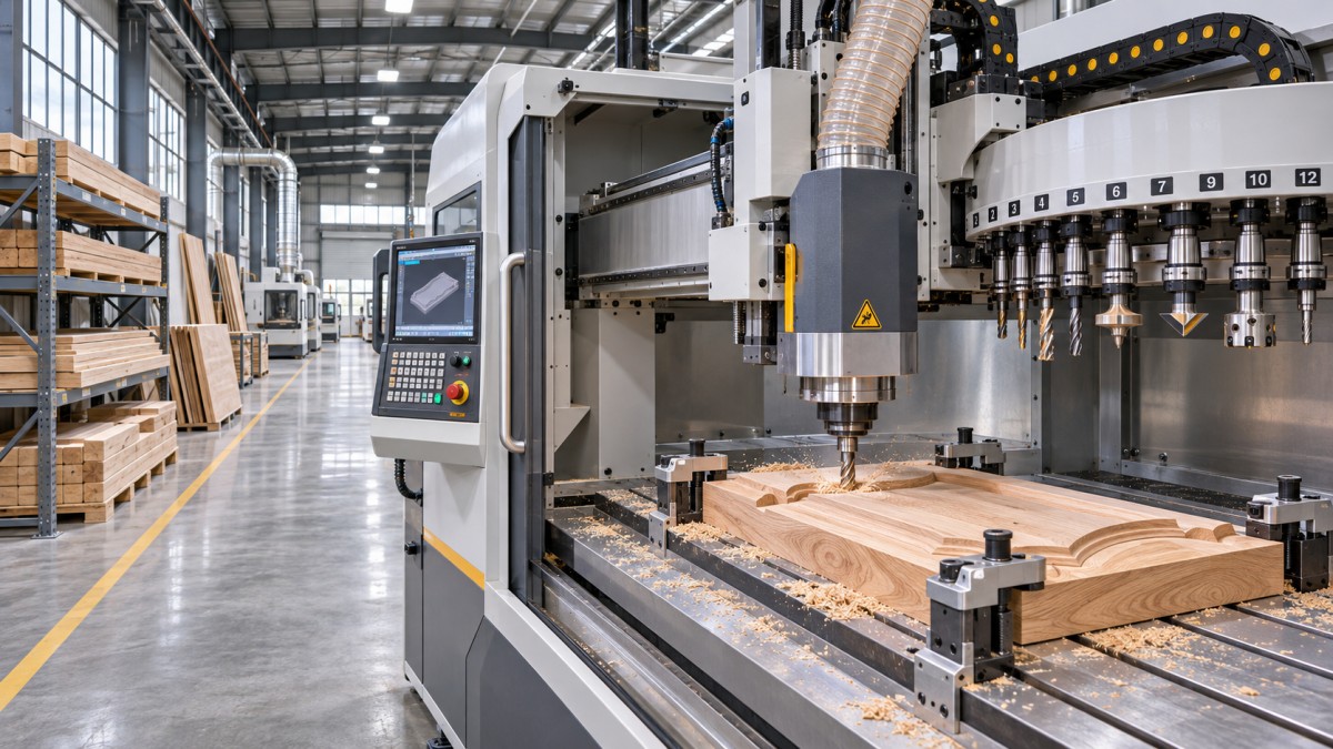
Choose spindle and tool capacity around representative parts, not the largest numbers in a catalog. The limiting operation is often a deep cut, demanding material, or complex setup.
List the materials, dimensions, tolerances, and required surface finishes for your highest-volume components. Include solid wood species, panel materials, coatings, and expected variations in moisture content.
For each part, map the operations in sequence: roughing, profiling, drilling, grooving, mortising, and finishing. Record the tools, cutting parameters, and setup changes each operation requires.
Then identify the jobs that consume the most production hours and those that create the highest instantaneous load. A machine must handle both without compromising quality.
Keep occasional future work separate from confirmed demand. Extra capacity has value, but purchasing it without a realistic workload can increase costs without improving throughput.
How Much Spindle Power Does Your Work Actually Need?
Spindle power supports material removal, but its usefulness depends on torque across the operating speed range. A higher kilowatt rating alone does not guarantee faster cutting.
Solid hardwood, large cutters, deeper passes, and aggressive feed rates generally increase cutting loads. Dense engineered panels and abrasive coatings can also influence tool wear and power demand.
Ask suppliers for the continuous spindle rating, peak rating, permitted peak duration, and speed range. Confirm whether published values refer to motor input or mechanical output.
Continuous power is especially important for sustained roughing. A peak rating may cover short load spikes but should not be treated as the machine's permanent operating capacity.
At a given rotational speed, the relationship is approximately power in kilowatts equals torque in newton meters multiplied by speed in revolutions per minute, divided by 9,550.
For example, delivering 3 kW at 12,000 rpm requires approximately 2.39 Nm at the spindle. This illustrates the relationship, not the spindle's actual available torque.
Real spindles have speed-dependent torque curves and thermal limits. Request the manufacturer's curve and check available torque at the cutting speeds your tools actually require.
For instance, a large-diameter cutter may need a lower rotational speed than a small router bit. The relevant question is whether adequate torque remains at that speed.
Also check toolholder limits, spindle bearings, machine rigidity, and workholding. Insufficient stiffness or clamping can cause vibration or part movement before the motor reaches its rated output.
How Do Cutting Parameters Affect Spindle Selection?
Power demand changes with cutter geometry, cutting width, depth of cut, feed rate, and material properties. Compare suppliers using the same proposed operation and tool specification.
Increasing feed can raise output, but excessive feed may overload the spindle or leave a poor surface. Reducing feed too far can promote rubbing and shorten tool life.
Spindle speed must suit the cutter diameter, tool rating, material, and desired chip load. A maximum speed specification is not a recommended speed for every operation.
For a cutter with multiple effective cutting edges, estimate feed per tooth by dividing feed rate by spindle speed and the number of effective cutting edges.
At 12,000 rpm, a two-flute cutter feeding at 6,000 mm per minute produces a nominal 0.25 mm feed per tooth. Actual settings require toolmaker validation.
Chip load alone does not predict power, finish, or tool life. Entry conditions, grain direction, tool sharpness, and how much of the cutter engages also matter.
Request a trial using your material, cutter, target finish, and proposed pass depths. Observe spindle load over the complete cycle, including demanding corners and tool entries.
A short trial cannot establish long-term reliability, but it can reveal obvious mismatches. For continuous production, discuss thermal stability and sustained duty with the supplier.
How Many Tool Positions Are Enough?
Tool capacity should cover the distinct tools needed for a realistic production schedule, including different diameters, profiles, drills, and finishing tools that cannot share one holder.
Build a tool list for a typical part family, then identify tools common across jobs. Count each required assembly, including separate tools used for roughing and finishing.
Consider a schedule requiring eight different tools across several parts. A magazine with eight usable positions may run it, but leaves no room for spare tools.
Additional positions can hold duplicates of high-wear cutters or accommodate less common jobs. Their economic value depends on how often they prevent stoppages or manual exchanges.
Check whether the advertised capacity means physical pockets or usable positions with your actual tool sizes. Large cutters may occupy adjacent space or require special arrangements.
Tool length, diameter, weight, and holder compatibility can restrict magazine loading. Confirm these limits against complete tool assemblies, not just the cutting edge dimensions.
A larger magazine does not automatically reduce every cycle time. It primarily helps when it avoids manual changes, setup interruptions, or splitting jobs into separate batches.
For high-mix production, assess how quickly operators can replace and identify tools between batches. Tool presetting, inventory control, and accurate offsets can matter as much as pocket count.
Should You Choose a Tool Changer or Multiple Spindles?
A tool magazine and multiple fixed spindles solve different problems. A magazine stores tool assemblies for automatic exchange; multiple spindles may carry different tools or machine concurrently.
Automatic tool changing offers flexibility when part programs need many distinct tools. Its value depends on change time, tool compatibility, and the number of changes per cycle.
Multiple spindles can suit repetitive operations on similar parts, especially when the machine can work on several positions at once. Confirm the actual head arrangement and control options.
For example, the CNC Mortising machine is intended for mortises, slots, grooves, and joints in solid wood and furniture components.
The supplied specifications list three or four 4.5 kW spindles, operating at 8,000 to 18,000 rpm. The individual spindle rating should not be mistaken for magazine capacity.
Listed processing lengths are 0–1,550 mm for the ZD-SC1500-3/4 and 0–2,200 mm for the ZD-SC2200-3/4; both list 135 mm width and 210 mm height.
These figures make the machines relevant to suitable long solid-wood components and door parts. Confirm actual clamping clearance, head operation, and achievable tolerances for your parts.
Do not assume simultaneous cutting, automatic tool changing, or a particular number of tool pockets from the spindle count. Ask the manufacturer to verify the configuration offered.
Calculate the Production Impact Before Comparing Prices
Estimate complete cycle time rather than focusing exclusively on cutting speed. Include loading, clamping, probing, cutting, tool changes, unloading, and any inspection required between parts.
For example, ten automatic changes at six seconds each add one minute per part. At 100 parts per shift, that represents 100 minutes of change time.
Those figures are illustrative, not an equipment specification. Some tool changes may occur alongside other actions, so measure the actual cycle rather than simply adding catalog values.
Compare the time saved by additional tools or spindles against their purchase and operating costs. Use expected production volume and realistic utilization, not maximum theoretical output.
Include tooling, holders, replacement cutters, dust extraction, compressed air, electrical infrastructure, maintenance, training, and installation. Check whether each item is included in the quotation.
Where a proposed machine saves setup time, calculate the benefit using expected changeovers per week and a documented labor or machine-hour rate. Avoid counting overlapping savings twice.
Evaluate downtime exposure as well. Confirm spare-parts availability, technical support arrangements, and recovery procedures for spindle faults, tool changer faults, and control system failures.
What Should a Supplier Demonstrate Before Acceptance?
Provide a representative part drawing, material specification, tolerance requirements, and finish criteria. Agree on the cutting tools and measurement method before requesting a machining demonstration.
Ask the supplier to document actual spindle speeds, feeds, pass depths, tool changes, and total cycle time. Record whether loading and unloading are included.
Inspect critical dimensions at multiple positions and check for tear-out, chatter, burns, and inconsistent joints. Repeat measurements on several parts rather than relying on one sample.
When workholding or moisture variation may affect results, include those conditions in the trial. Agree on acceptable variation and how rejected parts will be counted.
Request electrical requirements, air pressure and consumption, extraction needs, foundation details, and machine access clearances. Verify that your facility can support the proposed installation.
For the mortising models above, the supplied working air pressure is 0.7 MPa. Air consumption and other utility requirements should be confirmed for the selected configuration.
Finally, put the agreed machine configuration, acceptance tests, documentation, training, warranty terms, and service responsibilities in writing. Include a plan for resolving deviations before final acceptance.
Final Selection: Match Capacity to Verified Work
Select spindle power using the torque and duty required by your hardest sustained cuts, then validate the choice with representative materials, tooling, and measured results.
Size tool capacity around complete part families, realistic changeovers, and spare-tool needs. Compare magazine systems with multi-spindle arrangements according to the operations each must perform.
For any machine usinage bois investment, the strongest specification is one supported by a documented production trial, clear operating costs, and an agreed acceptance process.
Send Your Inquiry
We welcome your cooperation and we will develop with you.