


News & Exhibitions
Latest Factory Updates, Industry Trends & Global Exhibition Information
Choosing Solid Wood Finger Jointing Equipment for Stable Long-Length Blanks
A long solid-wood blank can look acceptable immediately after pressing and still fail later through open glue lines, uneven thickness, bowing, or visible joint telegraphing after machining. This is the practical risk behind selecting Solid Wood Finger Jointing Equipment: the machine is not only joining short pieces together, but establishing whether the finished blank will remain stable through planing, sanding, coating, transport, and service.
For technical evaluation, the most reliable selection principle is to assess the equipment as a controlled process rather than as a single cutting-and-pressing machine. Stable long-length blanks depend on accurate finger profiles, repeatable stock referencing, controlled adhesive application, synchronized transfer, and clamping pressure that is maintained until the joint is properly seated. A high nominal output rate has limited value if the line cannot hold these conditions across changing wood species, moisture levels, and part lengths.
Start with the blank specification, not the machine brochure
The correct equipment configuration begins with the product that must be produced. Before comparing machine layouts, define the blank dimensions, wood species, expected grain direction, acceptable defects, required joint appearance, and downstream machining allowance. A finger-jointed rail for a painted furniture frame has different tolerances from a visible hardwood panel component, a door stile, or a structural-length blank used in further lamination.
Evaluators should document the minimum and maximum input piece lengths as well as the target finished length. Short incoming pieces increase material recovery, but they also create more joints per blank and place greater demand on feeding, end trimming, and press synchronization. Wide variation in input dimensions can cause unstable referencing unless the line includes suitable sizing and alignment stages.
The following questions should be settled early:
- What finished cross-section must the blank achieve after planing or profiling?
- Will the joint remain visible, be covered by paint, or be machined into a decorative profile?
- Are pieces straight and square before finger cutting, or must the line compensate for irregular stock?
- Which wood species, densities, and moisture ranges will enter the process?
- Is production based on one repeated size or frequent changeovers between sections and lengths?
- Will the finished blank be edge-glued, laminated, mortised, shaped, or otherwise heavily machined afterward?
These answers determine whether a compact semi-automatic arrangement is sufficient or whether an integrated line with automated feeding, defect removal, end matching, pressing, and discharge control is justified. They also determine which tolerances must be specified in a factory acceptance test.
Finger profile accuracy is the foundation of joint strength
Finger geometry must be produced consistently from piece to piece. Even small variations in finger length, pitch, tip condition, or shoulder squareness can reduce contact area or prevent full seating under pressure. The result may be a joint that appears closed on one face but contains gaps internally. Such defects are often discovered only after surfacing exposes a glue-starved area or after seasonal movement places stress on the blank.
When reviewing cutter-head and machining arrangements, inspect how the stock is referenced before cutting. A machine that locates pieces from a consistent face and edge is generally easier to control than one that relies on irregular surfaces. Hold-down pressure, feed stability, spindle rigidity, and cutter accessibility all influence profile repeatability. Ask how worn cutters are identified and replaced, because a line that performs well with fresh tooling can become inconsistent as cutting edges deteriorate.
The end condition of the incoming lamella is equally important. A rough, torn, burned, or out-of-square end will not be corrected simply by adding adhesive. Equipment should include an effective trimming or preparation stage where needed, particularly when reclaimed offcuts, kiln-dried stock, or variable-width material is used. The goal is to present clean, accurately positioned material to the finger-cutting unit.
Do not assess the cutter pattern in isolation
Finger length and profile design should match the wood species, component section, required strength, and adhesive system. A deeper or more aggressive profile is not automatically better. Longer fingers can increase bonding area, but they may also increase machining load and demand more precise alignment. Fine profiles may suit certain smaller sections, yet they can be less forgiving when stock quality and feed control are inconsistent. The machine supplier should be able to explain the practical operating range of the proposed tooling rather than treating one finger pattern as universal.
Tooling maintenance should also be part of the selection discussion. Determine whether the cutter heads can be removed and reset without excessive setup time, whether the machine provides clear positioning references, and whether routine inspection can be completed safely. A technically capable line becomes difficult to operate when ordinary maintenance requires prolonged alignment work.
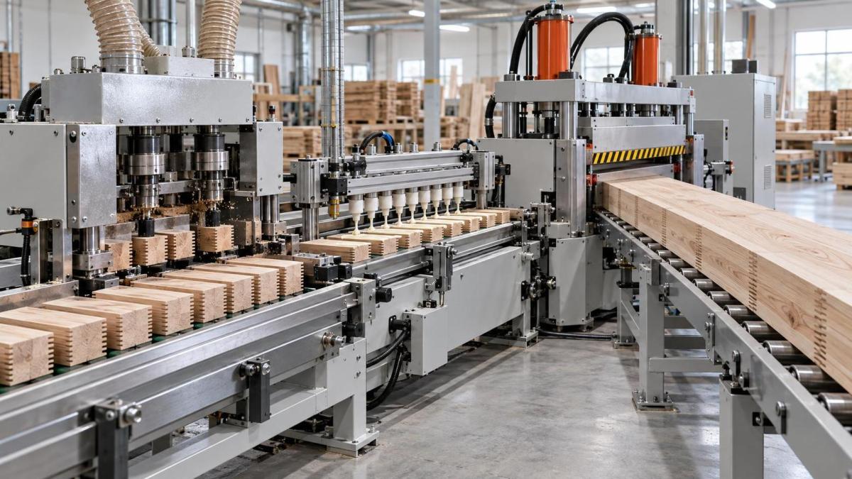
Adhesive control must match the press and production rhythm
Finger joints fail for different reasons than edge-glued panels. Adhesive must reach the mating finger surfaces without excessive buildup, dry-out, or contamination. Application consistency matters more than simply applying a large volume of glue. Too little adhesive can leave incomplete bond lines; too much can create squeeze-out, increase cleanup, and mask a poor fit during visual inspection.
Review the adhesive application method in relation to wood type, joint geometry, and line speed. The equipment should allow controlled, repeatable application and practical adjustment when adhesive viscosity or ambient conditions change. It should also be possible to clean the applicator without creating long interruptions or leaving cured residue that affects coverage.
Open assembly time deserves special attention. Once adhesive is applied, the pieces must travel through positioning and pressing within the adhesive manufacturer's permitted working window. A machine line with several transfers, accumulation areas, or manual interventions may look flexible but can create timing variation. This is especially relevant where long blanks require multiple pieces to be assembled before the final pressing cycle.
During evaluation, ask where the operator can observe adhesive presence before the joint closes. A process that provides no practical opportunity to notice skipped application can produce a high volume of defective blanks before the problem is detected. Simple visibility, accessible adjustment, and clear cleaning procedures are often more valuable than an overly complex application system.
Pressing performance is more than maximum force
Press specifications are frequently compared by force rating alone, but stable blanks require force to be delivered in the correct direction and maintained with repeatable positioning. End pressure seats the finger joint, while side and top restraint may be necessary to prevent offset, twisting, or movement in the blank during closure. The required arrangement depends on the blank section, species, surface condition, and finger geometry.
Examine how the press controls the following conditions:
- Axial alignment: The mating pieces should meet without lateral displacement that leaves a step after surfacing.
- Pressure repeatability: The system should apply comparable pressure from cycle to cycle, not only achieve a high peak load.
- Blank support: Long workpieces need support through entry, pressing, and discharge so their own weight does not influence joint alignment.
- Length control: The press or stop system should produce usable repeat lengths without accumulated dimensional error.
- Release timing: Premature release can disturb a newly formed joint, particularly when adhesive cure conditions are demanding.
A useful technical question is whether the machine can retain stable performance when the stock is near the upper and lower ends of the intended thickness range. Some systems handle nominal material well but become less accurate as dimensions vary. If production will include multiple sizes, request a demonstration or acceptance test that reflects that reality rather than a single ideal sample.
Material condition often explains “machine problems”
Finger jointing equipment cannot fully compensate for unsuitable lumber. Moisture variation, internal stress, end checks, resin pockets, knots near the joint zone, and distorted pieces all affect machining and bonding. A line may appear to have a pressing problem when the actual cause is stock that springs after cutting or changes shape after leaving the press.
Incoming material should be sorted according to the quality level needed for the end product. Pieces with severe warp may not sit correctly against machine references. End splits can extend into the finger area after trimming. Material with uneven moisture can move after jointing and create visible distortion in long blanks. These are production-control issues, but they should influence equipment selection because the proposed line must either reject unsuitable pieces, allow them to be trimmed, or tolerate a defined range of variation.
For long blanks used in furniture components, grain orientation and color selection may also matter. A technically sound joint can still be unsuitable if adjacent pieces create an unacceptable visual transition. Where appearance is important, consider how operators will identify, orient, and sequence pieces before automatic feeding removes the opportunity for correction.
Choose automation according to variation, not only output volume
Automation is valuable when it reduces handling variation and keeps the machining, gluing, and pressing stages synchronized. It is less valuable when the stock stream changes constantly and the line cannot be adjusted quickly. A highly automated setup can become inefficient if every new cross-section requires lengthy repositioning, tooling changes, or recalibration.
When comparing Solid Wood Finger Jointing Equipment, calculate labor needs around the entire work cell rather than focusing only on the operator at the press. Material loading, sorting, glue preparation, cutter maintenance, blank discharge, quality inspection, and rework handling all affect actual throughput. A line that minimizes one manual task while creating bottlenecks before or after the machine may not improve usable production.
Consider upstream and downstream machining interfaces
Finger-jointed blanks are rarely finished at the press. They usually move to planing, cutting, drilling, shaping, sanding, or assembly. The selected jointing equipment should leave enough machining allowance to remove minor surface offsets without reducing the required final section. It should also discharge blanks in a manner that avoids fresh-joint damage or stacking distortion.
In a line making profiled solid-wood parts, separate shaping equipment may follow blank preparation. A Spindle Moulder can be used for precision shaping, profiling, grooving, and edge processing after the blank has been jointed and stabilized. The ZD1170A configuration has a 1130 × 670 mm worktable, a maximum processing thickness of 120 mm, a 35 mm spindle diameter, spindle speeds of 8000/10000 r/min, and a 5.5 kW motor. These figures are relevant when checking whether downstream profiling capacity suits the blank size, but such a machine should not be treated as a substitute for dedicated finger cutting and pressing functions.
The interface between machines should be reviewed physically: transfer height, roller support, blank orientation, accumulation space, and the ability to isolate freshly pressed material where required by the adhesive process. Long blanks can be damaged by poor handling even when the joint itself is sound.
Use acceptance criteria that expose hidden instability
A technical evaluation should not end with a visual inspection of a few newly pressed pieces. Acceptance criteria need to address the conditions that reveal process variation. Inspect joint faces after surfacing, check for offset across the joint, verify finished length consistency, and examine whether glue coverage is continuous on representative test cuts. Where appropriate, test samples after the adhesive has cured under the conditions specified for the production process.
It is also useful to run samples that represent the intended operating range: thinner and thicker sections, shorter and longer input pieces, and the species most likely to challenge machining or bonding. The purpose is not to create an artificial worst-case demonstration, but to confirm that the chosen equipment is stable within the range it will actually be asked to handle.
Finally, assess fault recovery. A missed feed, damaged piece, empty adhesive condition, or cutter issue should be identifiable before it causes a long sequence of questionable blanks. Clear access for cleaning, safe adjustment points, and understandable machine feedback are practical selection factors because they determine how quickly normal production can be restored without losing control of joint quality.
Send Your Inquiry
We welcome your cooperation and we will develop with you.