


News & Exhibitions
Latest Factory Updates, Industry Trends & Global Exhibition Information
Shipping Woodworking Machines by Sea: Container Loading and Securing Plans
A workable sea-freight plan for woodworking machinery must answer three questions before loading starts: can each packed unit enter the container safely, can the container support the proposed weight distribution, and can the cargo be restrained throughout the journey? A machine that fits on a layout drawing may still be impossible to load through the doorway, difficult to secure, or inaccessible when the receiving team needs to unload it.
For project managers, the most useful deliverable is a coordinated loading and securing plan covering the machinery, its transport packaging, the container, and the handling equipment at both ends. Establish these details before confirming the container arrangement. Late changes to skids, machine orientation, or lifting access can affect freight costs and the installation sequence.
Build the plan around the packed machine
Start with a transport schedule for every machine and separate package. Catalogue dimensions are insufficient because operating dimensions and shipping dimensions serve different purposes. An edge bander may travel with selected assemblies removed; a CNC router may require protection around its gantry; a panel saw may have a separately packed sliding table. Each arrangement changes the space, handling, and restraint requirements.
For each shipping unit, record:
- Packed length, width, height, and gross weight, including the skid, crate, and attached accessories.
- Center of gravity, including any significant offset caused by motors, castings, or control cabinets.
- Approved lifting points, forklift pockets, and locations suitable for blocking or lashing.
- Required transport position and any restrictions on tilting, stacking, or loading against adjacent cargo.
- Removable assemblies, transport locks, and the actions required before commissioning.
Use the manufacturer’s instructions to distinguish structural attachment points from convenient-looking openings. A hole in a machine frame is not automatically a lifting point. Sheet-metal covers, extraction hoods, cable trays, and electrical cabinets should not become restraint points simply because they are accessible.
The packaging also needs a defined load path. If lashings attach to a skid, the machine must be adequately connected to that skid, and the skid must withstand the forces transferred through it. A substantial wooden base can still fail if its joints, machine fasteners, or lashing attachments are inadequate. Packing design and securing design therefore need to be reviewed together.
Choose the container after checking the loading route
Check the proposed equipment against the selected container’s actual specifications and condition. Internal space, door opening, available payload, floor loading limits, and securing-point capacities all matter. Extra internal height offers little benefit if the packed machine cannot pass through the opening or the handling equipment needs clearance above it.
Draw the movement into the container, including forklift mast clearance, lifting attachment height, turning space, and the point at which the machine transfers onto its final supports. A layout that assumes a forklift can place a heavy machine deep inside the container needs a separate check of the forklift’s access, operating capacity, and the container floor’s ability to support the loaded equipment.
Where an enclosed container cannot accommodate safe loading, compare an alternative packing arrangement with suitable special equipment. Open-top containers and flat racks introduce different exposure, handling, and securing requirements. Their suitability should be assessed as a complete transport arrangement rather than a simple solution to an oversized dimension.
Make the layout support loading, restraint, and unloading
Positioning the heaviest machine near the longitudinal center may help balance a load, but it does not establish that the arrangement is acceptable. Machinery often concentrates weight through a few feet or narrow skid runners. A container can remain within its total payload while carrying an unsuitable local floor load.
The plan should show where each machine bears on the floor and how the packaging spreads that load. Check the proposed supports against the selected container’s requirements. Adding timber beneath a machine is useful only when its dimensions, orientation, contact area, and strength provide an effective load path.
Review weight distribution across the container width as well as along its length. An apparently balanced layout can still place excessive weight on one side when a machine’s center of gravity is offset. The onward road movement also needs consideration because an acceptable container payload does not automatically establish compliance with the receiving route’s vehicle or axle limits.
Every significant load should appear on a numbered drawing. Show the machine outline, support positions, center-of-gravity location where known, blocking, lashing routes, and clearances needed to install and inspect the restraints. A plan view alone may conceal a high center of gravity or a lashing that bears against a vulnerable component; add side views where they resolve those questions.
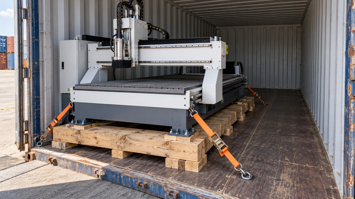
Loading sequence deserves equal attention. A crew may need to install blocking or connect lashings before the next machine occupies the working space. Narrow gaps that appear efficient on paper can prevent workers from reaching securing points or checking attachments. Space for restraint is part of the required cargo space.
Loose accessories need assigned positions and individual restraint. Tooling, pumps, spare motors, and assembly hardware should not be treated as convenient fillers between machines. Their packaging must protect adjacent equipment and remain secure if nearby crates settle or shift.
Plan the receiving operation before closing the layout
Confirm what the destination team can actually do. Forklift capacity depends on the load center and handling configuration, so the nominal capacity on its own is insufficient. Fork length, lifting height, doorway access, unloading surface, and space outside the container can all determine whether a machine can be removed safely.
A machine placed near the doors for early installation may obstruct access to another unit’s lashings. Conversely, loading a priority machine first can leave it unavailable until everything ahead of it has been removed. Resolve these conflicts while changing the drawing is still inexpensive.
If unloading depends on skates, pulling equipment, temporary platforms, or a crane, define the method and suitable attachment points in advance. Improvised pulling from a machine bed or gantry can damage alignment even when the cargo arrives without visible shipping damage.
Design securing around sliding and tipping
Woodworking machinery can move under braking, cornering, terminal handling, and vessel motion. Its weight alone does not establish stability. A heavy machine may slide on its supports, while a tall machine can overturn before sliding becomes the controlling problem.
The securing assessment should address movement in each relevant direction and resistance to tipping. It should use verified cargo weight, center of gravity, support geometry, friction assumptions, and the capacity of the complete restraint arrangement. The applicable transport conditions and securing guidance should be established by the party responsible for that assessment.
No reliable universal rule specifies a fixed number of straps per machine. Two machines of similar weight can require different arrangements because their height, support footprint, attachment points, and lashing angles differ. Where these inputs are uncertain, resolve them before loading rather than adding straps without checking what they achieve.
Give blocking and lashings defined jobs
Blocking can limit movement by transferring forces from the cargo into a suitable supporting structure. It must bear against areas capable of accepting those forces, with connections designed to keep it in position. Timber pressed against a light cover may damage the machine without providing effective restraint. Container side panels and doors should not be assumed to provide the required structural resistance.
Direct lashings connect suitable cargo attachment points to suitable container securing points. Their effectiveness depends on direction, angle, attachment strength, and the capacity of every component in the load path. An arrangement that controls sideways movement may contribute little to forward restraint.
Top-over lashings increase downward force and can contribute to frictional restraint, but their performance depends on maintained tension, contact conditions, and packaging strength. A crate that compresses or a support that settles can reduce their effectiveness. Protective wrapping may also alter friction, making unverified assumptions about contact surfaces unreliable.
Keep lashings clear of sharp edges and protect contact areas where necessary. Avoid routing them across precision tables, guideways, gantries, guards, or components that could bend under tension. If a proposed restraint risks changing machine geometry, revise the attachment arrangement.
Transport locks serve a separate purpose. They restrain moving assemblies within the machine, such as a gantry, carriage, or sliding table, according to the manufacturer’s instructions. They do not replace the restraint holding the complete machine to its transport base and the container.
Protect precision surfaces without trapping moisture
A sound securing plan can still deliver a machine with corrosion or moisture damage. Cast-iron tables, exposed machined surfaces, electrical assemblies, and precision motion components need protection appropriate to the transit, storage conditions, and packaging system.
Inspect the container before loading for water ingress, floor condition, contamination, and damage that could affect the cargo. Machinery and packaging materials should enter the container dry. Sealing damp timber or residual cleaning moisture inside a barrier can undermine the protection the barrier was intended to provide.
Choose compatible corrosion protection for exposed surfaces and record how it must be removed before operation. Where a sealed moisture-barrier package is used, its integrity and desiccant provision should suit the enclosed volume, materials, and expected exposure. Desiccant cannot compensate for liquid water entry or an ineffective seal.
Protect electrical enclosures and connectors without obstructing approved lifting or securing points. If packaging must be opened during loading to reach an attachment, include a method for restoring the protection afterward. Small tears around lashing routes can leave an otherwise carefully wrapped machine exposed.
Check destination requirements for any regulated wood packaging early enough to select suitable materials and obtain the necessary treatment or markings. Packaging compliance belongs in shipment preparation; discovering a problem after loading can require the cargo to be unpacked.
Release the shipment with a usable handover record
The final loading record should allow someone at the destination to understand how the cargo is supported, what must be removed, and which actions could create instability. Photographs are valuable when they show connections and supports clearly. A single image taken from the container doors rarely provides enough evidence.
Before dispatch, bring the following into one handover package:
- The final numbered layout and package list, updated for any changes made during loading.
- The securing arrangement, including attachment locations and the specifications of the restraint equipment used.
- Photographs of machine-to-skid connections, floor supports, blocking, lashings, and protected components before they become concealed.
- Instructions for unloading, removing transport locks, identifying loose assemblies, and preparing the machines for installation.
- Container identification and seal details linked to the shipment documents.
Assign responsibility for approving changes. Moving a machine a short distance can alter weight distribution, remove lashing clearance, or change the intended unloading sequence. The loading supervisor needs a clear route to the person authorized to assess those effects.
For a project manager commissioning woodworking machine sea freight support, the practical acceptance point is a plan that the packing crew can execute and the receiving crew can follow. Before the doors close, both teams should be able to identify how each machine is held, how its sensitive components are protected, and how it will leave the container in the condition required for installation.
Send Your Inquiry
We welcome your cooperation and we will develop with you.