


News & Exhibitions
Latest Factory Updates, Industry Trends & Global Exhibition Information
How to reduce edge chipping when drilling MDF panels
Clean MDF drilling starts with identifying where the damage occurs. Chipping around the entry face often points to the drill bit or its initial engagement with the surface. Damage at the exit of a through-hole calls for a closer look at backing support and breakthrough feed. Cracks or blowout at the panel edge may indicate that the hole is too close to the edge, the panel is moving, or the drilling operation is putting too much pressure on the surrounding material.
Before changing several settings on an MDF panel drilling machine, inspect a few defective pieces and compare them with a sound panel from the same job. The location and shape of the damage provide a practical starting point. A sharp, suitable bit, firm support and controlled feed will resolve many problems, but laminated faces, hole position and panel quality can all change the result.
Start by locating the damage
Keep the panel in its production orientation when inspecting it. Mark the drilling face and the direction of the cut so that entry and exit defects are not confused. Clean dust away from the hole before judging the edge.
- Chipping at the entry: Inspect the cutting edges and point of the bit, especially if the surface is melamine-faced or otherwise laminated. Also check whether the panel lifts or vibrates when the bit first makes contact.
- Breakout at the exit: Check whether the panel is supported directly beneath the hole and whether the bit pushes through too aggressively. This pattern is particularly relevant to through-holes.
- Damage spreading toward the panel edge: Check the hole-to-edge distance, clamping and the condition of the panel edge before adjusting the drill cycle.
- Fuzzy walls or a rough hole throughout: Look for a worn or unsuitable bit, poor chip evacuation, spindle runout or movement of the workpiece.
A defect may have more than one cause. For example, a bit that still produces an acceptable entry can break out the underside if the backing has become uneven. Equally, replacing the backing will not restore a damaged cutting edge.
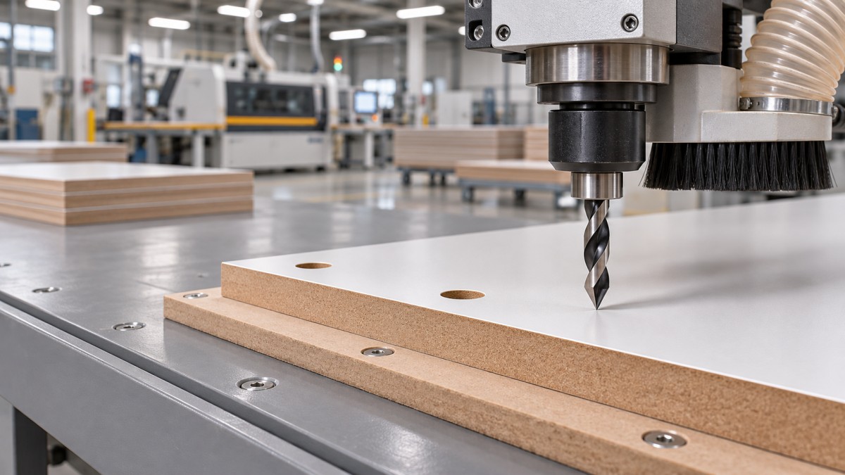
Check the bit before chasing machine settings
Remove the bit and inspect it under good light with the machine isolated according to the manufacturer’s procedure. Look for chipped cutting lips, a damaged point, resin buildup and uneven wear. Compare it with a known sharp bit of the same type. A bit can look intact at a glance yet leave a ragged rim because one cutting edge has lost its sharpness.
Use a drill geometry intended for the panel and hole being produced. For clean entry in faced panels, a sharp brad-point or dowel drill with effective outer spurs can help define the hole perimeter before the main cutting edges remove material. Check that the bit is suitable for the machine’s spindle rotation and mounting system. A left-hand and a right-hand bit are not interchangeable simply because their diameters match.
Bit selection also depends on the operation. A blind shelf-pin hole, a larger hardware bore and a through-hole do not necessarily call for the same geometry. Follow the tooling supplier’s recommendations for the material and hole type, then verify the result on an offcut from the production batch. Carbide tooling can be useful where wear is a concern, but carbide alone will not compensate for a chipped edge, unsuitable geometry or excessive runout.
When reinstalling a bit, clean the shank and holder, seat the tool as specified and tighten it with the correct equipment. Check for a bent shank, contamination in the holder or excessive spindle play if the hole is oversized or the damage is uneven around its circumference. Stop the machine before touching the tool; do not try to judge a rotating bit by hand.
Support the panel where the drill exits
For through-holes, the underside of the MDF becomes vulnerable as the bit approaches breakthrough. Without support, the remaining material can be pushed away before the cutting edges finish the hole. A flat sacrificial backing board placed tightly against the underside helps support those fibers and any facing material.
The backing needs attention as well. Repeated holes eventually leave an opening or a damaged area beneath the workpiece, reducing support exactly where it is needed. Shift or replace the backing when the drilling zone is no longer sound, and keep dust and chips from building up between it and the panel. Even a small gap can allow the panel to flex.
On a machine with a dedicated drilling table or fixture, use the support arrangement approved for that equipment. Make sure the programmed depth allows for the intended breakthrough without sending the tool into machine components, clamps or an unsuitable fixture. A backing board should be secured so it cannot move during the cycle.
Blind holes have a different priority: adequate support still prevents vibration, but the programmed depth and tool length must leave the specified material at the bottom. Check depth after changing bits or fixtures. Do not add a through-hole backing routine to a blind-hole job without reviewing the program and setup.
Control feed and keep the workpiece still
Feed that is too aggressive can load the bit and force material away at entry or exit. Feed that is too slow is not automatically better: it can increase rubbing, heat and dust buildup. Start with the tooling and machine manufacturer’s recommended operating range for the bit diameter and material, then adjust in small steps while inspecting the hole.
If the controller allows separate entry or breakthrough feed settings, a gentler approach at those points may help. Confirm that the programmed cycle actually reaches the intended depth and that cycle-time changes do not introduce a different problem, such as heat or packed dust. On simpler machines, use the available feed adjustment and a consistent operating cycle; do not override guards or attempt to hold the panel by hand near the bit.
Clamping is just as important as the numerical setting. The panel should sit flat against clean supports and remain secure through entry, drilling and tool withdrawal. Check that clamps apply sufficient pressure without marking or crushing the surface. For narrow parts, ensure the fixture supports the workpiece close enough to the hole without placing clamps in the tool path.
Dust accumulation can lift a panel off its support or interfere with chip removal. Clear the table and fixture as part of the setup, and check that the extraction system is operating as intended. Isolate the machine before clearing a blockage or reaching into the drilling area.
Pay particular attention to laminated faces and edge holes
A laminated surface can chip even when the MDF core looks clean. Because the face is comparatively brittle, the quality of the bit’s outer cutting edges and the stability of the panel at first contact matter. Inspect both the laminate and the core: a small chip in the decorative face may be unacceptable on a visible cabinet component even if the hole itself meets its dimensional requirement.
Protect the finished face from scratches caused by the table, clamps and loose chips. If the production sequence permits a choice of drilling direction, consider which face is visible and whether the other side has effective backing. Confirm the result on a sample; reversing the panel can move the defect from one surface to the other rather than eliminate it.
Holes close to an edge need enough sound material around them for the intended hardware and load. If blowout occurs toward the edge, inspect the panel for pre-existing damage and check that the part is clamped without flexing. A sharp bit and a less aggressive feed may reduce the drilling force, but they cannot guarantee a sound result where the hole position leaves too little material. If the design is marginal, raise it with the person responsible for the drawing or hardware specification before changing the location.
Also distinguish drilling damage from a damaged edge produced earlier in the process. Examine the panel before it reaches the drill, particularly around saw cuts and corners. For example, the CNC BEAM SAW ZD330F is a panel-cutting machine used for materials including MDF and laminated boards; it is an upstream cutting operation, not a substitute for drilling support or tool setup. A clean cut edge gives the operator a more reliable starting condition, but the drilling result still needs its own checks.
Make one change at a time and verify the result
When a job begins producing chips, separate affected parts and identify whether the problem is confined to one hole position, one spindle or all holes. On a multi-spindle machine, comparing holes made by different bits can quickly narrow the search. If only one position is defective, inspect that tool and holder first. If every position deteriorates together, look closely at panel support, clamping, material changes and shared machine settings.
Use an offcut with the same thickness, facing and orientation as the production part. Record the existing setup, then change one practical factor at a time: replace a suspect bit, renew the backing or adjust feed within the recommended range. Drill enough sample holes to inspect entry, exit, diameter and depth, not just the first acceptable rim. Return to production only when the result meets the job’s requirements.
During a run, check holes again after tool changes, fixture adjustments or a change in panel batch. If the defect returns gradually, tool wear or deterioration of the backing may be involved. If it appears suddenly, stop and check for a damaged bit, a loose holder, movement of the workpiece or a change in support. Keeping the defective part and its setup details makes the next inspection more useful than simply slowing the machine and hoping the problem disappears.
Send Your Inquiry
We welcome your cooperation and we will develop with you.