


News & Exhibitions
Latest Factory Updates, Industry Trends & Global Exhibition Information
How does a horizontal drilling center locate furniture panel edges?
A horizontal drilling center for furniture locates panel edges by registering the workpiece against physical stops, detecting its position with sensors, or combining both methods. The control system then relates that reference to the programmed drilling coordinates. The exact sequence depends on the machine: a sensor may confirm that a panel has reached a stop, measure an edge position, or perform a different detection task altogether.
This distinction matters when connector holes appear consistently offset or when panels of different sizes must run through the same setup. A drilling spindle can repeat its commanded movement accurately while the holes are still wrong relative to the panel, because the panel reference, program origin, or assumed panel dimensions are incorrect.
From a physical edge to a drilling coordinate
Horizontal drilling normally places holes into the narrow edge of a panel for dowels, connectors, or other fittings. To position a hole, the machine needs a reference along the panel edge and a reference for the drilling height through the panel thickness. Depending on its configuration, it may also need the location of another edge to establish panel width, orientation, or the position of holes on an opposite side.
A useful way to understand the process is to separate three coordinate systems:
- Machine coordinates: positions established by the machine’s axes and homing system.
- Workpiece datum: the physical edge, face, or corner from which a panel is located.
- Program coordinates: the hole positions specified relative to the selected datum.
The control must relate these systems correctly. A typical sequence is to home the axes, position the panel at the locating devices, secure it with clamps, and execute the drilling program using the defined workpiece origin. Some machines add an edge-search or measurement step before drilling. The order and available checks vary by design, so the operating sequence should be confirmed for the machine being assessed.
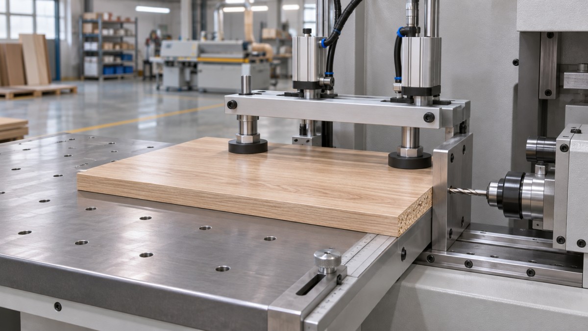
A panel can be held securely and still be referenced incorrectly. For example, if the program expects its origin at the left end but the operator locates the panel from the right, every hole may be displaced or mirrored. Secure clamping prevents movement; it does not establish that the correct edge was chosen.
Mechanical stops: a repeatable physical datum
On a mechanically referenced machine, the operator or feed mechanism brings the panel into contact with one or more stops. A stop at the end of the panel can establish the reference along its length. A fence or side reference may locate another edge, while the table surface or a supporting arrangement establishes the face used for height positioning.
Multiple contact points can also help control orientation. If a panel is intended to sit against a straight fence, contact at separated positions along that fence helps establish its alignment. A single point of contact may establish position at that point but does not, by itself, control rotation. The actual locating arrangement should therefore be examined as a complete system rather than as an isolated stop.
Mechanical stops are straightforward to inspect, but their result depends on the condition of both the machine and the panel. Chips trapped between the edge and stop shift the workpiece away from the intended datum. A damaged corner may touch in a different place from an intact one. An edge that is not straight can contact a fence locally while leaving the remainder of the panel out of alignment.
Clamping sequence matters too. If a clamp pulls or pushes the panel away from its reference during closure, the position before clamping is not necessarily the position during drilling. Watch the actual cycle, where it is safe to do so, and ask whether the design holds the panel against its references as clamping force is applied.
Sensor detection is not always edge measurement
Some drilling centers use sensors to detect a panel or confirm that it is present at a loading position. Others use a sensor or probe in a controlled search movement to identify an edge and update a workpiece coordinate. These functions should not be treated as equivalent.
A presence sensor may only provide an on/off signal: a panel is within its detection area. It may be useful for interlocking a cycle, but that does not establish a precise edge coordinate. A measurement function requires the control to associate a detected transition or contact event with a known axis position and apply the appropriate offset. Ask the supplier which of these functions is implemented and whether the measured value actually changes the drilling coordinates.
Contact and non-contact approaches
A contact probe or sensing mechanism can find an edge by touching it during a controlled movement. Its result depends on the contact surface, the condition of the edge, the probe’s repeatability, and the offset between the sensing point and the drilling tool. Contact devices may need clearance around the workpiece and must be protected from damage caused by unsuitable loading or incorrect setup.
Non-contact sensing can detect an edge without applying probing force, but performance depends on the sensor technology and the material presented to it. Surface finish, color, reflectivity, dust, and panel geometry can affect some optical detection methods. A sensor that reliably detects one panel surface is not automatically suitable for every coating or edge treatment. Verify the permitted materials and test representative panels rather than assuming that a general sensor description guarantees compatibility.
Hybrid systems use physical references and sensors for different purposes. A panel may be pushed to a stop while a sensor confirms presence, or a measured edge may be combined with a mechanical reference in another direction. Establish which device determines each coordinate and which merely verifies a condition. That distinction is essential when comparing automation claims.
Which edge does the program actually use?
Knowing that a machine can locate an edge is only part of the evaluation. The critical question is whether that edge is the same datum used in the part drawing and machining program. A hole dimensioned from the near end should be checked from that same end after machining; checking it from the opposite end introduces panel-length variation into the result.
Consider a hole specified at a fixed distance from one end. If the machine registers that end directly, variation at the far end need not change the hole’s distance from the registered end. If the machine instead registers the opposite end and calculates the hole position using a nominal panel length, any difference between actual and nominal length can affect the result. Measuring the actual length can address that issue only if the control uses the measurement correctly in its coordinate calculation.
Panel orientation introduces another source of error. Parts that look similar may have different finished faces, grain directions, or handed drilling patterns. Confirm whether the loading procedure, program selection, and machine references distinguish mirrored components. Also determine whether an operator must rotate or flip a panel for holes on another edge; each reloading step can introduce a new datum relationship.
The top and bottom faces deserve the same attention. A hole intended to be centered in the thickness may be programmed from a reference face, derived from an entered thickness, or positioned by another machine-specific method. A correct end reference cannot compensate for an incorrect thickness value or a panel face lifted from its support.
Upstream panel condition affects the reference
Edge location does not repair an incorrectly prepared panel. An out-of-square panel may register against a fence and an end stop, yet its opposite edges can remain displaced from their intended positions. Edge banding, localized damage, and residual cutting debris can also change where the panel contacts a reference.
For operations that prepare solid wood or other wooden components before drilling, straight and consistent cutting supports more predictable referencing. The Single blade rip saw, model MJ163, is intended for longitudinal cutting and uses a feeding system and circular saw blade for straight cutting. It is not an edge-location device for the drilling center, and a ripped edge should still be checked against the part’s dimensional and squareness requirements before it becomes a machining datum.
Diagnosing a hole-position discrepancy
Start by measuring from the same physical datum used by the program, not simply from the nearest convenient edge. Mark the reference face and end on a sample panel before loading it. Record the intended hole coordinate, the actual coordinate, and the direction of the discrepancy. Avoid changing machine offsets until the pattern is understood.
- Check the reference contact. Inspect the stop, fence, and panel edge for chips, damage, or gaps. Confirm that the panel remains seated after clamping.
- Verify the program origin. Check the selected part orientation, datum side, panel dimensions, and any workpiece or tool offsets used by the control.
- Repeat without changing the setup. Compare multiple cycles using suitable sample panels. A consistent shift suggests a datum or offset issue; varying results call for closer examination of seating, clamping, sensing, and movement.
- Separate panel error from machine error. Measure panel length, squareness, and edge condition independently. A hole can be correct from the registered end but appear wrong when measured from an inconsistent opposite end.
- Inspect the drilling system if the reference is sound. Tool condition, spindle alignment, and fixture movement can affect the produced hole even when the control has identified the intended edge position.
When the discrepancy changes with panel size, look for calculations that use a nominal dimension or a reference from the opposite edge. When it changes with surface finish or material, investigate the specified sensing method and whether contamination or the panel surface affects detection. These are diagnostic directions, not proof of a single cause.
Carry out inspection and adjustment under the machine manufacturer’s safety instructions. Do not reach into a moving or energized mechanism to observe stop contact or sensor operation. Calibration of machine coordinates, sensing offsets, or interlocks should follow the documented procedure for the specific equipment.
Evidence to request during equipment evaluation
A useful demonstration uses representative panels, the intended drilling program, and clearly identified measuring datums. Ask to see the full loading and clamping cycle, including any manual alignment, sensor search, or panel repositioning needed to complete the part. A short drilling cycle alone does not reveal the time required to establish the reference.
Request clarification on the following points before comparing specifications:
- Which edges and faces establish the workpiece origin for each supported operation?
- Are sensors used for presence confirmation, coordinate measurement, or both?
- How are different panel dimensions entered or measured, and are actual measurements applied to the program?
- What panel size, thickness, material, and edge-condition limits apply to the locating system?
- How are stops, sensors, and drilling tools calibrated relative to one another, and what routine checks are required?
- How are positioning and drilling accuracy specified and verified, including the reference datum and test conditions?
Distinguish axis positioning specifications from the accuracy of a completed hole relative to a furniture panel edge. The latter includes panel seating, datum transfer, clamping, tool position, and the measuring method. A comparison is meaningful only when the quoted values describe the same characteristic under comparable conditions.
Send Your Inquiry
We welcome your cooperation and we will develop with you.