


News & Exhibitions
Latest Factory Updates, Industry Trends & Global Exhibition Information
Panel Furniture Drilling Machines: Layout Choices for Faster Wardrobe Assembly
When a wardrobe assembly area begins to slow down, the visible bottleneck is often not the assembly bench. Fitters may be waiting for side panels, shelves, doors, or back panels that have been drilled correctly but released in the wrong sequence. In other cases, parts arrive with hole patterns that are technically accurate yet difficult to identify, sort, and join without repeated checking. The result is extra handling, delayed installation, avoidable rework, and pressure on the production schedule.
The most effective layout is usually the one that keeps panel flow aligned with the order of wardrobe assembly. A panel furniture drilling machine should not be selected only by spindle count or maximum processing speed. Its position, loading method, output direction, labeling process, and connection to cutting and assembly determine whether it actually shortens the time between panel cutting and finished wardrobe construction. For high-volume work, the practical choice is to match the machine layout to product mix, batch size, part complexity, and the level of production control already available.
Start with the assembly sequence, not the machine footprint
Wardrobes appear simple when viewed as finished products, but their panels move through several distinct operations. Side panels require rows of shelf holes and connector drilling. Top and bottom panels need joining holes. Fixed shelves, drawer components, partitions, doors, and back-panel supports each introduce different drilling patterns. The drilling layout should support the order in which these parts are prepared, rather than forcing operators to create a separate logistics system around the machine.
A useful starting point is to map the route of one typical cabinet body from panel cutting to final assembly. Identify where parts are cut, edged, drilled, labeled, sorted, and staged. Then look for points where a panel is lifted more than once, placed in a temporary stack, or sent backward to correct a missing hole. These points often reveal that the issue is not drilling capacity alone. It is a flow problem.
For example, a drilling station positioned far from the nesting or beam saw area may create a growing buffer of unprocessed panels. If the output then travels to another area for marking and sorting, assemblers may receive incomplete sets. A more compact arrangement can reduce travel distance, but it must still allow enough space for infeed, outfeed, panel rotation, quality checks, and safe material handling.
Three layout choices used in wardrobe production
The right configuration depends on how frequently wardrobe dimensions and internal structures change. A workshop producing repeated cabinet modules faces a different problem from a plant processing many custom room layouts each day.
Compact standalone drilling cell
A standalone cell places the drilling machine near the cutting and edge-banding operations, with manual or semi-assisted loading and unloading. It is often suitable where product designs vary, batch sizes are moderate, or floor space must be used carefully. Operators can process parts in defined batches and make program changes without disrupting a larger connected line.
This arrangement works best when parts are released to assembly as complete cabinet sets. Instead of drilling all side panels for the day and then all shelves, process the components for a manageable group of wardrobes together. That approach reduces sorting errors and makes it easier to discover a programming or material issue before it affects a large volume of parts.
The limitation is handling. Each panel may need to be oriented, loaded, removed, labeled, and transferred manually. When wardrobe volume rises, the machine may remain productive while operators become the restriction. Before adding more drilling capacity, check whether loading, panel turning, or output sorting is consuming the available cycle time.
Paired machines for parallel panel families
A paired layout uses two drilling stations with a defined division of work. One machine may handle cabinet carcass panels, while the other handles doors, drawer parts, or special components. Another approach is to split work by panel size or by drilling direction. The aim is not simply to run two machines at once; it is to prevent one type of recurring part from interrupting the flow of another.
This can be useful for wardrobes with a stable core structure but variable interiors. Side panels, top panels, bottoms, and fixed shelves can follow a predictable route, while drawer units, pull-out accessories, and custom partition details are processed separately. Assembly teams receive the main cabinet components on time even when optional items require extra drilling patterns.
The risk is creating two isolated queues. If machines are assigned without clear routing rules, operators may send parts to whichever station appears open, making tracking difficult. Machine programs, labels, and work orders need a consistent part-identification method so that drilled panels remain linked to the correct wardrobe configuration.
Connected line with automated transfer and return flow
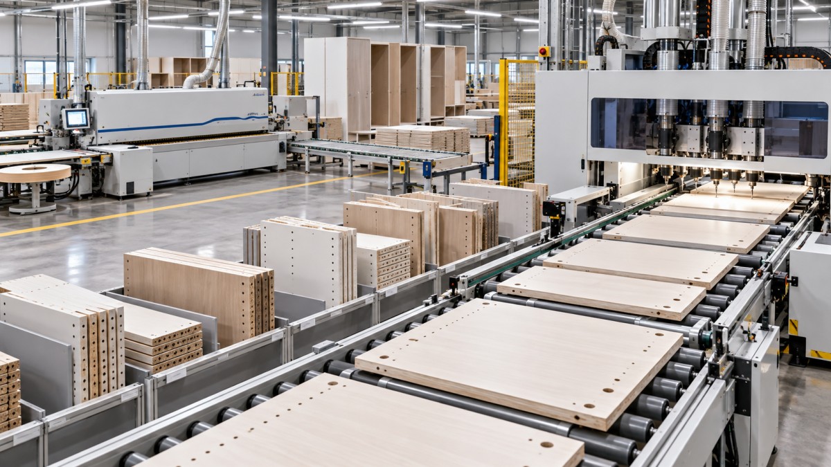
In a higher-volume environment, drilling can be integrated into a line with transfer systems, automatic infeed and outfeed, panel return devices, scanning, and connected production data. This arrangement is most valuable when the factory processes a continuous stream of panels and needs repeatable timing between cutting, edge treatment, drilling, and sorting.
Automated transfer does not remove the need for planning. It makes poor routing decisions happen faster. A line should be designed around the actual panel sequence: which face is presented first, whether the part requires turning, whether all edges are completed before drilling, and where the panel is identified after machining. A return flow can reduce manual panel handling, but it must be matched to the machine’s processing sequence and the physical orientation required for each hole pattern.
Keep drilling references consistent across the route
Fast wardrobe assembly depends on panels being drilled from the correct reference edges. A hole may be in the right position relative to one edge but wrong relative to the assembly orientation. This becomes especially important when left and right side panels are similar, when grain direction matters, or when parts have symmetrical dimensions but different hardware requirements.
Before finalizing a layout, define how each panel is referenced at every operation. The cutting process, edge-banding process, drilling program, label position, and assembly drawing should use the same orientation logic. A panel marked as “front-left” at cutting should not become “left side, reverse face” at drilling without a clear transfer rule.
Several details deserve attention:
- Reference edge selection: Use stable, clearly defined datum edges for connector holes, shelf-pin rows, hinge cups, and dowel patterns.
- Face identification: Distinguish the finished face, interior face, and reverse side before panels enter the drilling area.
- Handed components: Separate left and right panels in production data even where their outlines are nearly identical.
- Edge-band allowance: Confirm whether drilling dimensions are calculated from the raw panel edge or the finished edged panel.
- Label visibility: Place labels where they remain readable after drilling and do not interfere with inspection or assembly.
These controls may seem administrative, but they directly affect machine layout. A line that requires frequent manual interpretation of panel orientation will lose much of the benefit of automation. Conversely, a compact cell can perform reliably when operators receive unambiguous labels and consistent panel references.
Balance drilling capacity against upstream and downstream work
Installing a faster panel furniture drilling machine will not automatically accelerate wardrobe output if cutting, edge-banding, or assembly cannot release and absorb work at the same rate. Project planning should consider the complete route rather than evaluating each machine in isolation.
Upstream, the key question is whether cut and edged panels can arrive in an orderly sequence. Drilling mixed stacks forces operators to search for parts, interrupt programs, and make frequent orientation decisions. Downstream, assess whether drilled panels are immediately grouped into cabinet sets or simply placed into a general buffer. A large unstructured buffer hides problems until assembly begins, when the cost of finding a missing or incorrect part is higher.
A controlled buffer is different. It has a purpose: to absorb short variations between operations without losing part identity. For wardrobe production, buffers are often most useful after edge-banding and after drilling. The first protects the drilling machine from brief interruptions upstream. The second gives quality personnel or assembly teams a place to verify that a complete set of panels is available before construction begins.
Buffer size should not be treated as a fixed formula. Too little space can stop the line whenever a downstream team pauses. Too much space encourages excessive work in progress, makes damaged parts harder to identify, and increases the chance that panels from different wardrobe orders are mixed together. Marking buffer zones by work order, cabinet type, or release sequence provides more control than creating one large holding area.
Choose the drilling method around joint design and hardware variety
Wardrobe construction details should influence layout decisions early. Confirmat screws, dowels, cam-and-dowel fittings, shelf supports, concealed hinges, drawer slides, connector bolts, and rear-panel grooves each impose different drilling requirements. A product range using a limited set of repeatable joints can be organized around a highly standardized route. A range with frequent hardware changes needs more flexible programming and stronger verification before release.
Consider the following situations:
- A cabinet range with repeated 32 mm system holes may benefit from routing that keeps vertical side panels moving through the same reference process.
- Wardrobes with many hinged doors require hinge-cup drilling and mounting-hole positions to stay synchronized with door handing and carcass dimensions.
- Drawer-heavy designs can create a separate workload because slide positions, drawer-front clearances, and internal partitions may vary more than the basic carcass.
- Custom wardrobes with sloped tops, open niches, or mixed-depth sections may require a flexible cell where unusual panels can be checked before entering the main flow.
The decision is not whether standardization is better than flexibility. Both are needed in different proportions. The layout should ensure that standard parts move quickly without making special parts invisible or difficult to process correctly.
Plan for changeovers before they become a schedule problem
Wardrobe projects often involve changes in width, height, internal fittings, door style, and finish. Even when the panel construction remains similar, these changes can alter drilling programs, panel orientation, hardware positions, and labeling requirements. A layout that appears efficient for one product family may become unstable when several configurations are released together.
Program preparation should happen before panels reach the machine. Confirm drawing revisions, hardware specifications, panel thickness, finished dimensions, and reference conventions. The drilling operator should not be required to decide whether a revised shelf needs a different connector pattern while a queue of panels is waiting.
Where frequent changes are unavoidable, group production by shared characteristics where possible. Parts with common thickness, hardware logic, or drilling orientation can often be sequenced together without treating every wardrobe as an entirely separate setup. At the same time, do not group parts merely because they look similar. Two panels of identical size may belong to different configurations and require different hole patterns.
Use inspection points that protect assembly time
Inspection should focus on errors that would interrupt assembly, not only on whether a hole exists. A quick check after drilling can confirm hole location, depth, diameter, panel orientation, and visible surface condition. It can also verify that edge-banded faces have not chipped and that labels still match the panel.
For new programs, revised hardware, unfamiliar materials, or unusual panel shapes, inspect an initial part before releasing the batch. Check the part against the assembly requirement rather than relying only on the drilling screen or program name. A correct program can still be associated with the wrong panel revision or material thickness.
During steady production, inspection frequency should reflect the risk of the operation. Repeated standardized shelf panels may need less intensive checking than handed door panels with hinge drilling or parts requiring multiple faces to be processed. When a defect is found, isolate related panels by order and program version before continuing. Continuing to drill while the source remains unclear can turn a small setup issue into a larger sorting and replacement task.
Layout decisions that improve daily control
The best production layout is usually easy to understand from the shop floor. An operator should know where panels come from, which orientation they require, where completed parts go, and how exceptions are handled. Assemblers should receive complete, identifiable panel sets rather than a mixture of generic drilled components.
For a compact operation, this may mean placing a small verification and sorting area directly beside the drilling output. For a larger line, it may mean defining controlled transfer points, scan confirmations, and short buffers between machining stages. In both cases, the objective is the same: reduce the time spent searching, turning, rechecking, and correcting panels after they have already left the drilling station.
When reviewing layout options, prioritize the route of the panel over the appearance of the equipment arrangement. A drilling station that supports consistent references, sensible buffers, clear part identity, and cabinet-set release will usually contribute more to faster wardrobe assembly than a higher-capacity machine placed in a disconnected workflow.
Send Your Inquiry
We welcome your cooperation and we will develop with you.