


News & Exhibitions
Latest Factory Updates, Industry Trends & Global Exhibition Information
How Six-Sided CNC Drilling Machines Keep Cabinet Panel Holes Aligned
A cnc 6 sided drilling machine keeps cabinet panel holes aligned by relating drilling operations on different faces to a controlled coordinate system. Alignment depends on how the panel is referenced, held, moved, and matched to its machining program. Access to six faces reduces handling between operations, but the resulting accuracy still depends on the machine configuration, panel condition, tooling, and calibration.
For cabinet assembly, two relationships matter: the position of each hole relative to the panel’s assembly datums, and the position of mating holes after separate panels are brought together. A machine can produce repeatable hole spacing while placing the entire pattern at the wrong distance from an edge. Evaluating alignment therefore requires more than a repeatability figure.
Alignment begins with the panel datum
A panel datum is the reference used to locate machining features. In cabinet work, this usually involves a designated face and reference edges that correspond to the intended assembly. The machine establishes these references through stops, clamping positions, sensing, or a combination of these methods. The exact arrangement varies with the feed system and drilling layout.
The program must interpret those references consistently. A shelf connector hole dimensioned from the cabinet’s front edge must remain tied to that edge when the corresponding side panel is machined. If one program references the front and another references the rear, variation in panel depth transfers directly into assembly mismatch.
Actual panel size and programmed panel size are separate inputs. Where a machine measures panel dimensions, the software must define how those measurements affect hole coordinates. A feature located from the far edge may require compensation for measured length. A feature dimensioned from the near reference edge should retain its specified offset. Applying a general correction to every hole can move features that were already correctly referenced.
Edge banding adds another reference decision. Dimensions taken from the finished edge differ from dimensions taken from the substrate edge. The machining file, panel orientation, and process sequence must agree on which surface defines the coordinate origin.
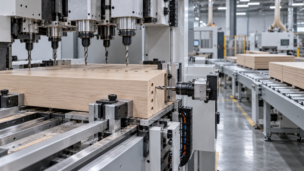
A useful datum diagram shows the reference face, front edge, feed direction, and corresponding hole coordinates on both mating panels. It makes mirrored parts and opposing edge holes easier to interpret than separate face drawings without orientation marks.
What coordinated machining preserves across six faces
Six-sided machining provides access to the two broad faces and four edges through the machine’s available drilling units and positioning movements. This does not establish that every face is drilled simultaneously or that the panel remains in one unchanged clamping position. Some layouts require transfers between clamps or successive movements through the working area.
The alignment advantage comes from maintaining a known relationship between the panel and the machine throughout those movements. Manual turning and repositioning introduce fresh opportunities for referencing the wrong edge, seating against debris, or reversing a part. Coordinated machining reduces those interventions while keeping face and edge operations linked to the same part definition.
However, a clamp transfer is still a positioning event. When one gripper releases and another takes over, the panel must retain its intended position or be accurately referenced again. A transfer-related error often appears as a step between groups of holes made before and after the handover. A repeated pattern distributed along a long panel is useful for exposing this behavior.
Drilling heads must share a calibrated coordinate relationship
Each spindle or drilling unit has a physical offset from the machine coordinate system. Calibration connects its actual tool position to the commanded hole location. If the upper and lower drilling units have inconsistent offsets, holes on opposing faces can disagree even though each unit produces internally consistent patterns.
Horizontal drilling introduces a further relationship: spindle height relative to the panel’s reference face. An edge hole intended to intersect a face hole needs the correct longitudinal position, height, and depth. Agreement in a top-view drawing alone does not establish that the two bores will meet correctly.
For connectors that require intersecting bores, inspection should establish whether the bore axes meet as intended and whether the connector seats correctly. Enlarging a bore to accommodate an offset can conceal the positioning fault while weakening the intended fit.
Clamping controls whether axis accuracy reaches the workpiece
A servo axis positions the machine mechanism. The panel follows accurately only when its contact with the grippers and supports remains stable. Dust on a gripping surface, worn pads, or insufficient holding force allows movement that an axis encoder does not directly detect.
Clamping force also has an upper practical limit. Excessive pressure can mark a surface, compress a vulnerable edge, or distort a thin panel. The appropriate setting depends on the gripping arrangement, panel construction, and machining forces. A setting established for a thick, dense panel should not automatically carry over to a thinner component.
Support matters especially during edge drilling. A bowed panel may sit correctly at the gripper while lifting near the drilling point. The resulting bore can have the intended machine coordinates yet lie at the wrong height relative to the local panel face. Local hold-down devices and support surfaces need to control the region where cutting occurs.
Tool condition affects this relationship. A worn drill increases thrust and can encourage movement or deflection. On coated particleboard, a clean entry surface does not prove that the bore remains correctly positioned through its depth. Tool projection, spindle condition, and chip clearance also influence the finished bore.
Servo specifications describe only part of the error
Command resolution, positioning accuracy, and repeatability describe different properties. Fine command increments do not demonstrate equally fine hole placement. Repeatability describes the consistency of repeated moves under stated conditions; positioning accuracy concerns agreement with the intended position. Neither figure alone includes every effect of clamping, tool runout, panel distortion, and drilling load.
The measurement method behind a published specification matters. Axis measurements taken without cutting describe a different condition from holes drilled across a production-sized panel. Results obtained over a short movement near the center of travel do not establish performance across the full working range.
These patterns guide diagnosis; they do not establish a cause by themselves. Repeating the same machining path with controlled changes to support, tooling, or gripping helps distinguish errors that otherwise look similar.
Program orientation must survive every face transformation
Cabinet machining files contain more than coordinates. They also carry assumptions about the reference face, part orientation, tool direction, and whether a component is left-handed or right-handed. The conversion from design data to machine instructions must preserve those assumptions.
Opposing faces are a common source of errors. A hole shown from the outside of a cabinet side requires a coordinate transformation when machined from the opposite face. An incorrect mirror operation can produce a neat, repeatable pattern on the wrong side of the intended reference line.
Symmetrical test parts conceal some of these faults. A more revealing trial panel contains an asymmetric pattern with distinguishable features near different edges. Its drawing should identify the reference face and front edge explicitly. Processing matching left and right components then exposes incorrect mirroring or face assignment.
Tool mapping deserves the same attention. A program can call the correct coordinates while selecting a drill with an unsuitable diameter, length, or orientation. Where multiple spindles produce related holes, their individual offsets must remain associated with the correct tool positions after maintenance or tool replacement.
Measure the relationships that assembly actually needs
An acceptance trial should reproduce the features that constrain the cabinet joint. A dowel connection requires compatible bore positions and a suitable fit. A cam connection adds relationships between the cam pocket, connecting bore, and mating fastener. Shelf pin rows require consistent pitch and a common front-edge reference across opposing cabinet sides.
Hole position measurements need a defined reference method. Measuring from a rough edge, or locating a bore center from a chipped opening, introduces uncertainty unrelated to machine motion. Suitable gauges, pins, or coordinate measurement methods should locate the functional feature and reference the same surfaces used by the drawing.
A practical trial sequence separates several questions:
- Establish the panel’s actual dimensions, thickness, and squareness before machining. Otherwise, a cutting error can be mistaken for a drilling error.
- Repeat an asymmetric pattern on several panels with the same loading orientation to assess consistency.
- Extend the pattern across the working length and include features that require a clamp handover, where applicable.
- Machine mating components and assemble the specified hardware. Record forced engagement, incomplete seating, and panel displacement alongside dimensional measurements.
Include representative materials and thicknesses because gripping and support conditions change with panel construction. A short, flat sample provides limited evidence for a long or bowed component. Trial conditions should also record tooling, feed settings, extraction, and machine warm-up state so that later comparisons remain meaningful.
Acceptance limits should come from the joint design and the agreed inspection method. There is no single hole-position tolerance suitable for every cabinet connection. Clearance, engagement length, hardware geometry, and the combined variation of mating parts determine the allowable error. Two panels can each satisfy an individual dimensional limit while their errors act in opposite directions and prevent assembly.
Keeping alignment stable after initial setup
Calibration remains useful only while the mechanical and referencing conditions remain consistent. Chips at stops, damaged gripping pads, loose tool mounting, and changes to drilling-unit offsets can alter results after a successful trial. A retained reference program with known, measurable features provides a direct way to detect such changes.
After a tool collision, spindle adjustment, clamp repair, or software change affecting coordinate conversion, the verification should target the relationship disturbed by that work. Replacing a horizontal drilling unit calls for confirmation of bore height and its relationship to face holes; changing part-orientation logic calls for asymmetric left and right components.
Recording measured deviations by feature location makes gradual drift and sudden shifts distinguishable. That evidence connects an assembly problem to a specific positioning relationship, allowing the correction to address its source.
Send Your Inquiry
We welcome your cooperation and we will develop with you.