


News & Exhibitions
Latest Factory Updates, Industry Trends & Global Exhibition Information
How Do You Avoid Compatibility Problems in a Turnkey Woodworking Line?
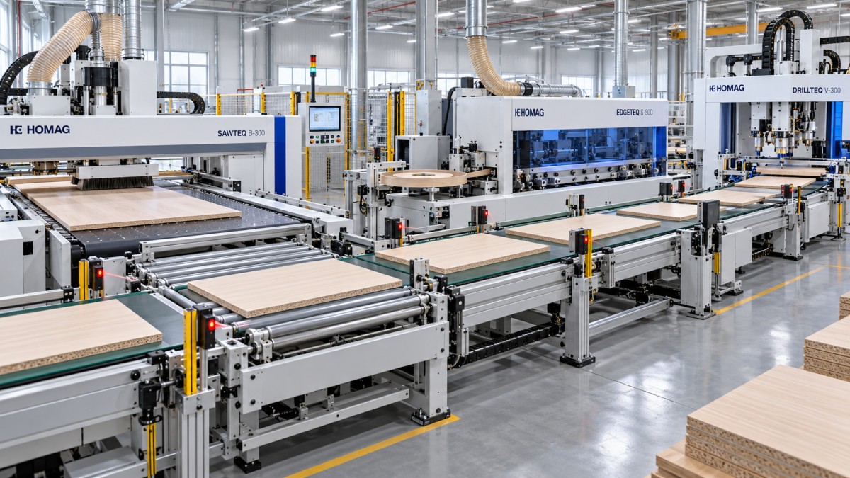
Compatibility problems in a turnkey woodworking line are avoided by treating the line as one production system before any individual machine is selected. Panel feeding, cutting, edge banding, drilling, sorting, and discharge must agree on throughput, workpiece reference, data format, transfer direction, and operating conditions. A machine can perform well on its own and still create bottlenecks, damaged edges, positioning errors, or unexplained stoppages when it is connected to equipment with different assumptions.
The practical starting point is a complete process definition: the panel materials, thickness range, minimum and maximum workpiece dimensions, finished product mix, daily changeover pattern, edge material, hole patterns, required output, and available floor space. These details determine whether equipment will communicate and transfer parts reliably. A line designed around only nominal machine speed often fails because the slowest handling action, not the fastest cutting action, sets the usable output.
Match real throughput, not brochure capacity
Every station has a rated capacity, but those figures are meaningful only under stated conditions. A panel saw may list a high feed speed for long, uniform panels, while an edge bander reaches its stated speed only with a stable edge tape, limited trimming operations, and few workpiece gaps. A drilling or nesting station may require additional time for tool changes, panel alignment, barcode reading, or program loading. If these conditions are ignored, the upstream machine releases parts faster than the next station can accept them.
Calculate capacity from the expected product mix rather than one ideal panel. Include loading time, machining time, travel between stations, queue time, orientation changes, inspection, rework handling, and planned tool changes. Short cabinet components, narrow strips, shaped parts, and frequent order changes often reduce effective line output much more than large rectangular panels.
A small speed difference can be absorbed by a correctly sized buffer. A large or variable difference cannot. When a fast cutting station feeds a slower edge bander without enough accumulation space, panels may stack incorrectly, arrive with insufficient spacing, or force repeated stop-start cycles. The result is often blamed on the transfer conveyor even though the root cause is an unrealistic capacity match.
Establish one reference system for every part
Many compatibility failures appear as random machining defects but are actually reference conflicts. One machine may locate a panel from the left edge and front edge, while the next process assumes the opposite face or a different corner as zero. This becomes especially serious with door panels, drawer components, mirrored cabinet sides, and parts that need machining on more than one face.
Define the workpiece reference before programming the line. The definition should identify the panel face, leading edge, trailing edge, machine-side edge, operator-side edge, grain direction, and permitted rotation. It should also state what happens after a turner, cross conveyor, or manual intervention. A label alone is not enough when the label can be covered, removed, scanned from only one side, or applied before a part changes orientation.
Drilling patterns are particularly vulnerable. A dowel hole or connector hole may be correct relative to the original cut reference but wrong after a panel is flipped. The defect can remain hidden until assembly, where mating parts no longer align. Programs should therefore use a controlled part identity linked to its orientation, rather than relying on a visual assumption that the panel entered the machine correctly.
Reference consistency also includes edge treatment. If only selected edges receive banding, the production data must identify those edges in the same coordinate convention used by the edge bander and drilling station. Otherwise, hardware positions near a finished edge can be offset, or an edge may be processed twice while another is missed.
Control interfaces before discussing automation
Physical connection is only one layer of compatibility. A conveyor can move panels between stations while data exchange remains incomplete. The line needs agreement on machine-ready signals, fault signals, part-present detection, emergency-stop behavior, queue status, and recovery after an interruption. Without this agreement, a station may send a panel forward before the receiving station has cleared its infeed, or a restart may cause the same part to be processed twice.
Review the control architecture in detail. Identify which controller owns each conveyor zone, which device starts and stops material movement, how blocked conditions are communicated, and whether a fault in one machine should stop the entire line or only prevent new parts from entering a specific zone. The answer is different for a short linked cell and for a line with sufficient buffer capacity.
Data compatibility deserves the same attention. Cutting optimization, labeling, edge banding, drilling, and routing may each use a different file structure or machine program. Confirm how part IDs, dimensions, material codes, grain direction, edge codes, machining operations, priority, and revision status are transferred. A successful import of a sample file does not prove that all production fields are interpreted correctly. Some fields may be ignored, shortened, converted, or assigned a default value.
Program revision control prevents another frequent problem: a cutting list is updated, but downstream drilling data remains from an earlier version. The line then produces parts that appear normal until assembly reveals a mismatch. Each released job should carry one identifiable revision, and the system should prevent mixed revisions from running together without deliberate authorization.
Recovery logic matters after a stop
Normal production is rarely the difficult condition. The critical test is what happens after a jam, a panel rejection, a scanner failure, a tool alarm, or a power interruption. The line must distinguish between a panel that has been cut, a panel that has entered edge banding, a panel waiting in a buffer, and a panel already completed. If the system loses that state information, restarting can create duplicate machining, skipped operations, or mixed batches.
A useful recovery procedure records the exact location and status of each affected part, then makes the restart sequence explicit. For example, parts remaining in a buffer may need to be cleared or re-identified before new production is released. A rejected panel should not silently disappear from the job count when replacement parts are generated. These are process rules as much as software rules.
Make material handling compatible with the actual panel range
Transfer equipment is often specified around maximum panel dimensions, yet minimum dimensions and surface condition cause more difficulty. Narrow rails, short components, thin panels, lightweight honeycomb boards, high-gloss surfaces, veneered panels, and slightly bowed sheets respond differently to rollers, belts, vacuum devices, side guides, and pushers.
Check the complete path rather than each transfer point separately. A small part may be stable on an outfeed belt but rotate when crossing a gap into a side transfer. A large panel may fit through the line but flex enough to trigger unreliable sensors or interfere with guides. Parts with protective film can alter friction; freshly edge-banded components may be more vulnerable to marks if they are pushed against an accumulation stop.
Vacuum lifting and automatic loading require compatible panel surface, thickness, porosity, and separation behavior. Rough, textured, perforated, or warped boards may need different suction arrangements from smooth melamine-faced panels. If manual loading is retained at one point, the machine interface must still prevent a part from entering in the wrong orientation or at an unsafe time.
Buffer design should reflect the reasons parts wait. A buffer used only for routine speed balancing can be simple. A buffer that also holds panels during tool changes, downstream alarms, or batch sorting needs more controlled tracking. Too little buffer causes frequent line stops; too much buffer without reliable identification can hide sequencing errors until a large group of parts is out of order.
Verify utilities, environment, and installation geometry
Compatibility extends beyond the workpiece. Electrical supply, compressed air quality, extraction capacity, network layout, floor level, access clearance, and service space influence whether connected machines run consistently. A line can be mechanically aligned during installation and later drift into faults because extraction is inadequate at one station, pneumatic pressure falls during peak use, or dust enters sensors and electrical enclosures.
Dust extraction needs to be considered as a shared system. A high-demand machine can reduce airflow available to another station when both run at the same time. Poor extraction affects cut quality, edge preparation, sensor reliability, and the cleanliness of moving components. The issue is not solved by confirming that every machine has an extraction port; duct sizing, branch layout, gate behavior, and simultaneous demand must be evaluated together.
Floor conditions also affect transfer accuracy. Long conveyor sections and precision drilling equipment need appropriate leveling and anchoring. A slight height mismatch between machines can cause repeated edge contact, panel skew, or unstable handoff. Leave space for opening electrical cabinets, changing tools, cleaning glue systems, accessing sensors, and removing a jammed panel. A layout that fits on paper can become difficult to maintain once guards, cable routes, and extraction ducts are installed.
Use acceptance testing to expose line-level conflicts
Testing individual machines is necessary but insufficient. A meaningful acceptance run uses representative materials and part sizes, including common difficult components such as narrow pieces, short panels, mirrored parts, and panels requiring multiple edge or drilling operations. It should include normal flow, planned changeover, an interrupted barcode read, a downstream blockage, and restart after an alarm.
During testing, watch for more than finished part quality. Record queue formation, sensor behavior, orientation accuracy, label readability, idle time, machine-to-machine handoff, rejected-part handling, and whether job status remains correct after a stop. A line that produces a few correct panels under close supervision may still have unresolved recovery or tracking issues.
- Run at least one mixed job rather than a sequence of identical panels, because varying dimensions and operations reveal transfer and data-order problems.
- Compare the released production data with the machining result at each station. This exposes missing edge codes, incorrect rotations, and program fields that were not transferred.
- Deliberately pause a receiving station while upstream equipment is active. Observe whether the buffer, controls, and panel tracking respond in the intended order.
- Inspect parts after assembly-related operations, not only at machine outfeed. Hole position, handedness, and edge selection are easier to judge against their mating components.
Keep compatibility stable after commissioning
A compatible line can become incompatible through small uncoordinated changes. New panel thicknesses, different edge tape, revised labels, altered tool libraries, replacement sensors, software updates, and new product constructions can change how stations interact. Treat any change that affects dimensions, reference, timing, or part data as a line change rather than a local adjustment.
Document the agreed operating window for each connected process: permitted panel range, reference convention, minimum spacing, buffer rules, barcode position, data fields, utility requirements, and restart procedure. When a recurring problem appears, trace the first point where the part, signal, or data diverged from that definition. This approach separates a genuine machine fault from a mismatch introduced by material, program, handling, or installation conditions.
The most reliable turnkey woodworking lines are built around verified interfaces. When capacity, reference logic, control signals, part data, transfer behavior, and recovery procedures are defined together, each station supports the next one instead of creating a hidden dependency that only becomes visible during production.
Send Your Inquiry
We welcome your cooperation and we will develop with you.